Engine Unit -- Inspection |
| 1. INSPECT VALVE LASH ADJUSTER ASSEMBLY |
- NOTICE:
- Keep the lash adjuster free from dirt and foreign objects.
- Only use clean engine oil.
Place the lash adjuster into a container full of engine oil.
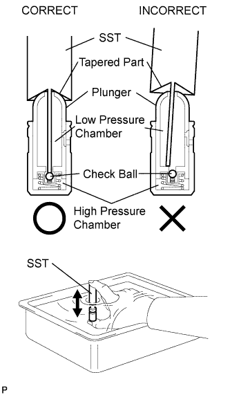 |
Insert the SST's tip into the lash adjuster's plunger and use the tip to press down on the check ball inside the plunger.
- SST
- 09276-75010
Squeeze the SST and lash adjuster together to move the plunger up and down 5 to 6 times.
Check the movement of the plunger and bleed the air.
- OK:
- Plunger moves up and down.
- NOTICE:
- When bleeding high-pressure air from the compression chamber, make sure that the tip of SST is actually pressing the check ball as shown in the illustration. If the check ball is not pressed, air will not bleed.
After bleeding the air, remove SST. Then try to quickly and firmly press the plunger with a finger.
- OK:
- Plunger is very difficult to move.
| 2. INSPECT CAMSHAFT |
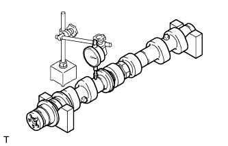
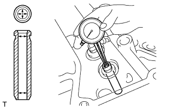
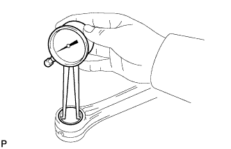
Inspect the camshaft for runout.
Place the camshaft on V-blocks.
Using a dial indicator, measure the circle runout at the center journal.
- Maximum circle runout:
- 0.04 mm (0.0016 in.)
- HINT:
- Check the oil clearance after replacing the camshaft.
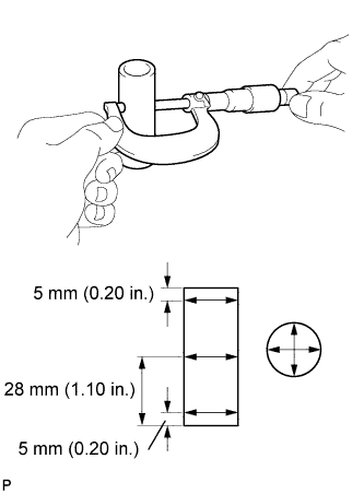
Using a micrometer, measure the cam lobe height.
- Standard cam lobe height:
Item Specified Condition Intake 44.316 to 44.416 mm (1.7447 to 1.7487 in.) Exhaust 44.262 to 44.362 mm (1.7426 to 1.7465 in.)
- Maximum cam lobe height:
Item Specified Condition Intake 44.166 mm (1.7388 in.) Exhaust 44.112 mm (1.7367 in.)
 |
Using a micrometer, measure the journal diameter.
- Standard journal diameter:
Item Specified Condition No. 1 journal 35.946 to 35.960 mm (1.4152 to 1.4157 in.) Other journals 25.959 to 25.975 mm (1.0220 to 1.0226 in.)
 |
| 3. INSPECT CAMSHAFT TIMING GEAR ASSEMBLY |
Clamp the camshaft in a vise.
- NOTICE:
- Be careful not to damage the camshaft in the vise.
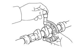
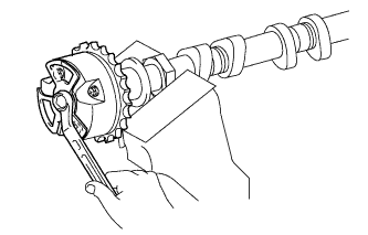
Put the camshaft timing gear and camshaft together by aligning the key groove and straight pin.
 |
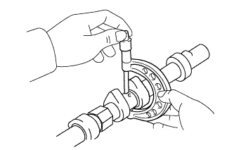
Lightly press the gear against the camshaft, and turn the gear. Push further at the position where the pin enters the groove.
- NOTICE:
- Be sure not to turn the camshaft timing gear in the retard direction (the right angle).
Check that there is no clearance between the gear's fringe and the camshaft.
Tighten the flange bolt with the camshaft timing gear secured in place.
- Torque:
- 100 N*m{1020 kgf*cm, 74 ft.*lbf}
 |
Check the lock of the camshaft timing gear.
Clamp the camshaft in a vise, and confirm that the camshaft timing gear is locked.
- NOTICE:
- Be careful not to damage the camshaft.
Release the lock pin.
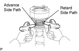
Cover the 4 oil paths of the cam journal with vinyl tape as shown in the illustration.
- HINT:
- The 4 oil paths are located in the groove. Plug 2 paths with rubber pieces as shown in the illustration.
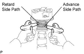
Prick a hole in the tape placed on the advance side path. Prick a hole in the tape placed on the retard side path on the opposite side to that of the advance side path, as shown in the illustration.
Apply approximately 200 kPa (2.0 kgf/cm2, 28 psi) of air pressure to the two opened paths.
- CAUTION:
- Cover the paths with a piece of cloth when applying pressure to keep oil from splashing.
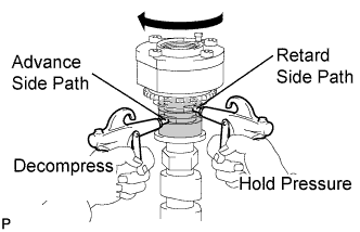
Check that the camshaft timing gear revolves in the advance direction when reducing the air pressure applied to the retard side path.
- HINT:
- This operation releases the lock pin for the most retarded position.
When the camshaft timing gear reaches the most advanced position, release the air pressure first from the retard side path and advance side path, in that order.
- NOTICE:
- Do not release the air pressure from the advance side path first. The gear may abruptly shift in the retard direction and break the lock pin.


Check for smooth rotation.
Turn the camshaft timing gear within its movable range (21°) 2 or 3 times, but do not turn it to the most retarded position. Make sure that the gear turns smoothly.
- NOTICE:
- Do not use air pressure to perform the smooth rotation check.
Check the lock in the most retarded position.
Confirm that the camshaft timing gear is locked at the most retarded position.
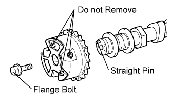
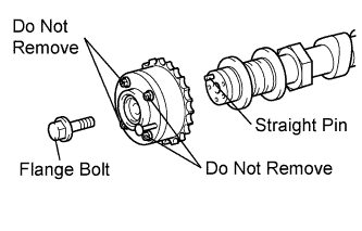
Remove the flange bolt and camshaft timing gear.
- NOTICE:
- Be sure not to remove the other 3 bolts.
- If planning to reuse the gear, be sure to release the straight pin lock before installing the gear.
 |
| 4. INSPECT CAMSHAFT TIMING EXHAUST GEAR ASSEMBLY |
Clamp the camshaft in a vise.
- NOTICE:
- Be careful not to damage the camshaft in the vise.
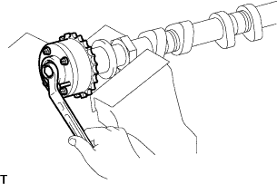
Put the camshaft timing exhaust gear and camshaft together by aligning the key groove and straight pin.
|
Lightly press the gear against the camshaft, and turn the gear. Push further at the position where the pin enters the groove.
- CAUTION:
- Be sure not to turn the camshaft timing exhaust gear in the retard direction (the right angle).
Check that there is no clearance between the gear's fringe and the camshaft.
Tighten the flange bolt with the camshaft timing exhaust gear fixed in place.
- Torque:
- 100 N*m{1020 kgf*cm, 74 ft.*lbf}
 |
Check the camshaft timing exhaust gear lock.
Make sure that the camshaft timing exhaust gear is locked.
Release the lock pin.
Cover the 4 oil paths of the cam journal with vinyl tape as shown in the illustration.
- HINT:
- The 4 oil paths are located in the groove. Plug 2 paths with rubber pieces as shown in the illustration.
Prick a hole in the tape placed on the advance side path. Prick a hole in the tape placed on the retard side path on the opposite side to that of the advance side path, as shown in the illustration.
Apply approximately 200 kPa (2.0 kgf/cm2, 28 psi) of air pressure to the two opened paths.
- CAUTION:
- Cover the paths with a piece of cloth when applying pressure to keep oil from splashing.
Make sure that the camshaft timing exhaust gear turns in the retard direction when reducing the air pressure applied to the advance side path.
- HINT:
- The lock pin is released and the camshaft timing exhaust gear turns in the retard direction.
When the camshaft timing exhaust gear moves to the most retarded position, release the air pressure from the advance side path, and then release the air pressure from the retard side path.
- NOTICE:
- Be sure to release the air pressure from the advance side path first. If the air pressure of the retard side path is released first, the camshaft timing exhaust gear may abruptly shift in the advance direction and break the lock pin or other parts.

Check for smooth rotation.
Turn the camshaft timing exhaust gear within its movable range (18.5°) 2 or 3 times, but do not turn it to the most advanced position. Make sure that the gear turns smoothly.
- NOTICE:
- When the air pressure is released from the advance side path and then from the retard side path, the gear automatically returns to the most advanced position due to the advance assist spring operation and locks. Gradually release the air pressure from the retard side path before performing the smooth rotation check.
Check the lock at the most advanced position.
Make sure that the camshaft timing exhaust gear is locked at the most advanced position.
Remove the flange bolt and camshaft timing exhaust gear.
- NOTICE:
- Be sure not to remove the other 3 bolts.
- If planning to reuse the gear, be sure to release the straight pin lock before installing the gear.
 |
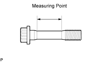
| 5. INSPECT CYLINDER HEAD SET BOLT |
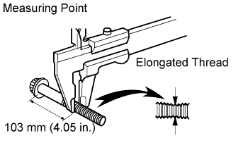
Using a vernier caliper, measure the minimum diameter of the elongated thread at the measuring point.
- Minimum outside diameter:
- 10.70 mm (0.4213 in.)
- HINT:
- If a visual check reveals no excessively thin areas, check the center of the bolt (see illustration) and find the area that has the lowest diameter.
- If the diameter is less than the minimum, replace the cylinder head bolt.
 |
| 6. INSPECT CHAIN SUB-ASSEMBLY |
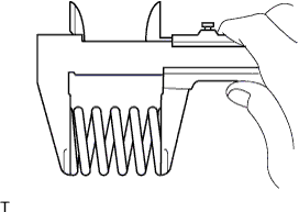
Using a spring scale, pull the chain with a force of 147 N (15 kgf, 33 lbf) as shown in the illustration.
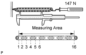 |
Using a vernier caliper, measure the length of 16 links.
- Maximum chain elongation:
- 136.9 mm (5.389 in.)
- NOTICE:
- Perform the measurement at 3 random places. Use the average of the measurements.
| 7. INSPECT NO. 2 CHAIN SUB-ASSEMBLY |
Pull the chain with a force of 147 N (15 kgf, 33 lbf) as shown in the illustration.
|
Using a vernier caliper, measure the length of 16 links.
- Maximum chain elongation:
- 137.6 mm (5.417 in.)
- NOTICE:
- Perform the measurement at 3 random places. Use the average of the measurements.
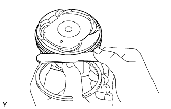
| 8. INSPECT CRANKSHAFT TIMING GEAR OR SPROCKET |
Place the chain around the sprocket.
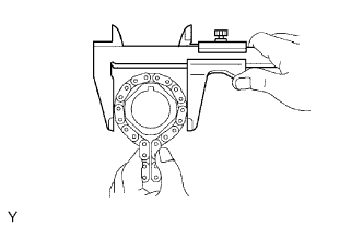 |
Using a vernier caliper, measure the sprocket diameter with the chain.
- Minimum sprocket diameter (w/ chain):
- 61.4 mm (2.417 in.)
- HINT:
- The vernier caliper must contact the chain rollers for the measurement.
- If the diameter is less than the minimum, replace the chain and sprocket.
| 9. INSPECT IDLE SPROCKET ASSEMBLY |
Place the chain around the sprocket.
 |
Using a vernier caliper, measure the sprocket diameter with the chain.
- Minimum sprocket diameter (w/ chain):
- 61.4 mm (2.417 in.)
- HINT:
- The vernier caliper must contact the chain rollers for the measurement.
- If the diameter is less than the minimum, replace the chain and sprocket.
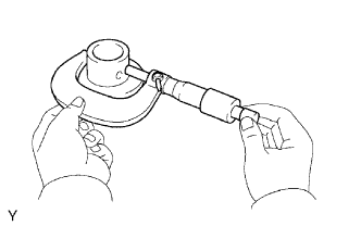
| 10. INSPECT IDLE GEAR SHAFT OIL CLEARANCE |
Using a micrometer, measure the idle gear shaft diameter.
- Standard idle gear shaft diameter:
- 22.987 to 23.000 mm (0.9050 to 0.9055 in.)
 |
Using a caliper gauge, measure the inside diameter of the idle gear.
- Standard idle gear inside diameter:
- 23.02 to 23.03 mm (0.9062 to 0.9067 in.)
 |
Subtract the idle gear shaft diameter measurement from the idle gear inside diameter measurement.
- Standard oil clearance:
- 0.02 to 0.043 mm (0.0008 to 0.0017 in.)
- Maximum oil clearance:
- 0.043 mm (0.0017 in.)
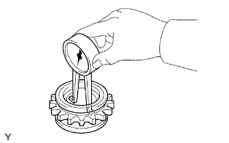
| 11. INSPECT NO. 1 CHAIN TENSIONER ASSEMBLY |
Move the stopper plate upward to release the lock. Push the plunger and check that it moves smoothly.
If necessary, replace the chain tensioner.
 |
| 12. INSPECT NO. 2 CHAIN TENSIONER ASSEMBLY |
Check that the plunger moves smoothly.
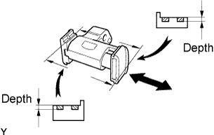 |
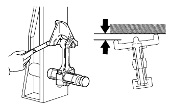
Measure the worn depth of the chain tensioner.
- Maximum depth:
- 0.9 mm (0.035 in.)
| 13. INSPECT NO. 3 CHAIN TENSIONER ASSEMBLY |
Check that the plunger moves smoothly.
 |
Measure the worn depth of the chain tensioner.
- Maximum depth:
- 0.9 mm (0.035 in.)
| 14. INSPECT CHAIN TENSIONER SLIPPER |
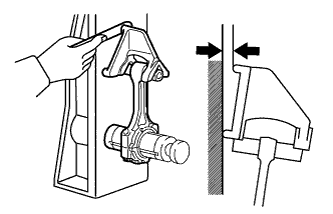
Measure the worn depth of the chain tensioner slipper.
- Maximum depth:
- 1.0 mm (0.039 in.)
 |
| 15. INSPECT NO. 1 CHAIN VIBRATION DAMPER |
Measure the worn depth of the chain vibration damper.
- Maximum depth:
- 1.0 mm (0.039 in.)
 |
| 16. INSPECT NO. 2 CHAIN VIBRATION DAMPER |
Measure the worn depth of the chain vibration damper.
- Maximum depth:
- 1.0 mm (0.039 in.)
 |
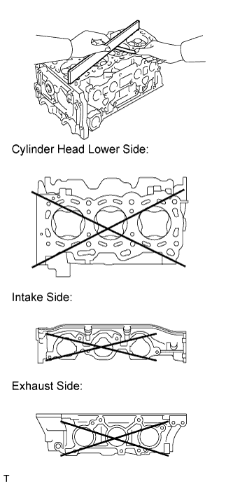
| 17. INSPECT CYLINDER HEAD SUB-ASSEMBLY |
Using a precision straightedge and feeler gauge, measure the warpage of the contact surface of the cylinder block and manifolds.
- Standard warpage:
Item Specified Condition Cylinder head lower side 0.05 mm (0.0020 in.) Intake side 0.08 mm (0.0031 in.) Exhaust side 0.08 mm (0.0031 in.)
- Maximum warpage:
- 0.10 mm (0.0039 in.)
 |
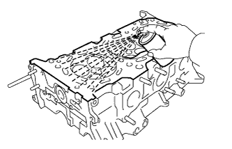
Using a dye penetrate, check the intake ports, exhaust ports and cylinder surface for cracks.
If cracked, replace the cylinder head.
 |
| 18. INSPECT INTAKE VALVE |
Using a micrometer, measure the diameter of the valve stem.
- Standard valve stem diameter:
- 5.470 to 5.485 mm (0.2154 to 0.2159 in.)
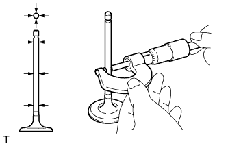 |
Using a vernier caliper, measure the valve head margin thickness.
- Standard margin thickness:
- 1.0 mm (0.0394 in.)
- Minimum margin thickness:
- 0.50 mm (0.0197 in.)
 |
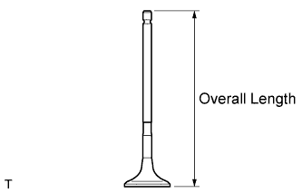
Using a vernier caliper, measure the valve's overall length.
- Standard overall length:
- 105.85 mm (4.1673 in.)
- Minimum overall length:
- 105.35 mm (4.1476 in.)
 |
| 19. INSPECT EXHAUST VALVE |
Using a micrometer, measure the diameter of the valve stem.
- Standard valve stem diameter:
- 5.465 to 5.480 mm (0.2151 to 0.2157 in.)
 |
Using a vernier caliper, measure the valve head margin thickness.
- Standard margin thickness:
- 1.0 mm (0.0394 in.)
- Minimum margin thickness:
- 0.50 mm (0.0197 in.)
 |
Using a vernier caliper, measure the valve's overall length.
- Standard overall length:
- 110.40 mm (4.3464 in.)
- Minimum overall length:
- 109.90 mm (4.3268 in.)
 |
| 20. INSPECT INTAKE VALVE SEAT |
Apply a light coat of Prussian blue to the valve face.
 |
Lightly press the valve face against the valve seat.
Check the valve face and valve seat by using the following procedure.
If Prussian blue appears around the entire valve face, the valve face is concentric. If not, replace the valve.
If Prussian blue appears around the entire valve seat, the guide and valve face are concentric. If not, resurface the valve seat.
Check that the valve seat contacts in the middle of the valve face with the width between 1.1 and 1.5 mm (0.043 and 0.059 in.).
| 21. INSPECT EXHAUST VALVE SEAT |
Apply a light coat of Prussian blue to the valve face.
|
Lightly press the valve face against the valve seat.
Check the valve face and valve seat by using the following procedure.
If Prussian blue appears around the entire valve face, the valve face is concentric. If not, replace the valve.
If Prussian blue appears around the entire valve seat, the guide and valve face are concentric. If not, resurface the valve seat.
Check that the valve seat contacts in the middle of the valve face with the width between 1.2 and 1.6 mm (0.047 and 0.063 in.).
| 22. INSPECT INNER COMPRESSION SPRING |
Using a vernier caliper, measure the free length of the inner compression spring.
- Standard free length:
- 45.46 mm (1.7898 in.)
 |
Using a steel square, measure the deviation of the inner compression spring.
- Maximum deviation:
- 1.0 mm (0.039 in.)
- Maximum angle (reference):
- 2°
 |
| 23. INSPECT VALVE GUIDE BUSH OIL CLEARANCE |
Using a caliper gauge, measure the inside diameter of the guide bush.
- Standard bush inside diameter:
- 5.51 to 5.53 mm (0.2169 to 0.2177 in.)
 |
Subtract the valve stem diameter measurement from the guide bush inside diameter measurement.
- Standard clearance:
Item Specified Condition Intake 0.025 to 0.060 mm (0.0010 to 0.0024 in.) Exhaust 0.030 to 0.065 mm (0.0012 to 0.0026 in.)
- Maximum oil clearance:
Item Specified Condition Intake 0.08 mm (0.0031 in.) Exhaust 0.10 mm (0.0039 in.)
- HINT:
- If the clearance is greater than the maximum, replace the intake valve and intake guide bush.
- If the clearance is greater than the maximum, replace the exhaust valve and exhaust guide bush.
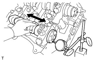
| 24. INSPECT CAMSHAFT THRUST CLEARANCE |
Inspect the bank 1 camshafts.
Install the bank 1 camshafts.
Using a dial indicator, measure the thrust clearance while moving the camshaft back and forth.
- Standard thrust clearance:
- 0.08 to 0.13 mm (0.0031 to 0.0051 in.)
- Maximum thrust clearance:
- 0.15 mm (0.006 in.)
Inspect the bank 2 camshafts.
Install the bank 2 camshafts.
Using a dial indicator, measure the thrust clearance while moving the camshaft back and forth.
- Standard thrust clearance:
- 0.08 to 0.13 mm (0.0031 to 0.0051 in.)
- Maximum thrust clearance:
- 0.15 mm (0.006 in.)
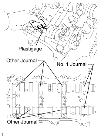
| 25. INSPECT CAMSHAFT OIL CLEARANCE |
Clean the bearing caps, camshaft housing and camshaft journals.
 |
Place the camshafts on the camshaft housing.
Lay a strip of Plastigage across each of the camshaft journals.
Install the bearing caps.
- NOTICE:
- Do not turn the camshaft.
Remove the bearing caps.
Measure the Plastigage at its widest point.
- Standard oil clearance:
Item Specified Condition No. 1 journal 0.040 to 0.079 mm (0.0016 to 0.0031 in.) Other journals 0.025 to 0.062 mm (0.0010 to 0.0024 in.)
- Maximum oil clearance:
Item Specified Condition No. 1 journal 0.10 mm (0.0039 in.) Other journals 0.09 mm (0.0035 in.)
 |
Clean the bearing caps, camshaft housing and camshaft journals.
Place the camshafts on the camshaft housing.
Lay a strip of Plastigage across each of the camshaft journals.
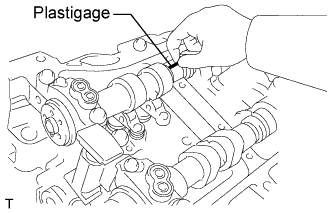 |
Install the bearing caps.
- NOTICE:
- Do not turn the camshaft.
Remove the bearing caps.
Measure the Plastigage at its widest point.
- Standard oil clearance:
Item Specified Condition No. 1 journal 0.040 to 0.079 mm (0.0016 to 0.0031 in.) Other journals 0.025 to 0.062 mm (0.0010 to 0.0024 in.)
- Maximum oil clearance:
Item Specified Condition No. 1 journal 0.10 mm (0.0039 in.) Other journals 0.09 mm (0.0035 in.)
 |
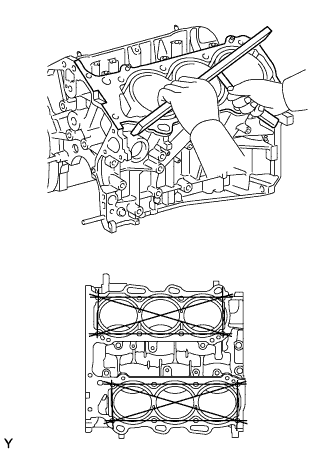
| 26. INSPECT CYLINDER BLOCK FOR WARPAGE |
Using a precision straightedge and feeler gauge, measure the warpage of the contact surface of the cylinder head gasket.
- Maximum warpage:
- 0.07 mm (0.0028 in.)
 |
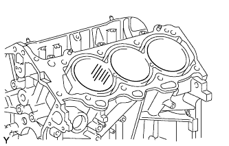
Visually check the cylinder for vertical scratches.
If deep scratches are present, rebore all 6 cylinders. If necessary, replace the cylinder block.
 |
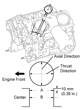
| 27. INSPECT CYLINDER BORE |
Using a cylinder gauge, measure the cylinder bore diameter at positions A and B in the thrust and axial directions.
- Standard diameter:
- 94.000 to 94.012 mm (3.7008 to 3.7013 in.)
- Maximum diameter:
- 94.200 mm (3.7087 in.)
 |
| 28. INSPECT PISTON SUB-ASSEMBLY WITH PIN |
Using a micrometer, measure the piston diameter at right angles to the piston center line where the distance from the bottom edge of the piston is as specified.
- Distance:
- 9.8 mm (0.3858 in.)
- Standard diameter:
- 93.960 to 93.980 mm (3.6992 to 3.6999 in.)
- Minimum diameter:
- 93.830 mm (3.6941 in.)
 |
| 29. INSPECT PISTON OIL CLEARANCE |
Measure the cylinder bore diameter in the thrust direction.
Subtract the piston diameter measurement from the cylinder bore diameter measurement.
- Standard oil clearance:
- 0.020 to 0.052 mm (0.0007 to 0.0020 in.)
- Maximum oil clearance:
- 0.06 mm (0.0024 in.)
| 30. INSPECT RING GROOVE CLEARANCE |
Using a feeler gauge, measure the clearance between a new piston ring and the wall of the ring groove.
- Standard ring groove clearance:
Item Specified Condition No. 1 0.020 to 0.070 mm (0.0008 to 0.0028 in.) No. 2 0.020 to 0.060 mm (0.0008 to 0.0024 in.) Oil 0.070 to 0.150 mm (0.0028 to 0.0059 in.)
 |
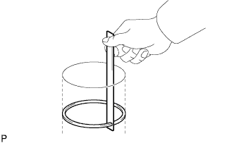
| 31. INSPECT PISTON RING END GAP |
Insert the piston ring into the cylinder bore.
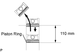 |
Using a piston, push the piston ring a little beyond the bottom of the ring travel, 110 mm (4.33 in.) from the top of the cylinder block.
Using a feeler gauge, measure the end gap.
- Standard end gap:
Item Specified Condition No. 1 0.25 to 0.35 mm (0.0098 to 0.0138 in.) No. 2 0.50 to 0.60 mm (0.0197 to 0.0236 in.) Oil 0.10 to 0.40 mm (0.0039 to 0.0157 in.)
- Maximum end gap:
Item Specified Condition No. 1 0.50 mm (0.0197 in.) No. 2 0.85 mm (0.0335 in.) Oil 0.60 mm (0.0236 in.)
 |
| 32. INSPECT PISTON PIN OIL CLEARANCE |
Check each mark on the piston, piston pin and connecting rod.
 |
Using a caliper gauge, measure the inside diameter of the piston pin hole.
- Standard piston pin hole inside diameter:
Mark Specified Condition A 22.001 to 22.004 mm (0.8662 to 0.8663 in.) B 22.005 to 22.007 mm (0.8663 to 0.8664 in.) C 22.008 to 22.010 mm (0.8665 to 0.8665 in.)
 |
Using a micrometer, measure the piston pin diameter.
- Standard piston pin diameter:
Mark Specified Condition A 21.997 to 22.000 mm (0.8660 to 0.8661 in.) B 22.001 to 22.003 mm (0.8662 to 0.8663 in.) C 22.004 to 22.006 mm (0.8663 to 0.8664 in.)
 |
Subtract the piston pin diameter measurement from the piston pin hole diameter measurement.
- Standard oil clearance:
- 0.001 to 0.007 mm (0.00004 to 0.0003 in.)
- Maximum oil clearance:
- 0.015 mm (0.0006 in.)
- HINT:
- If the oil clearance is greater than the maximum, replace the piston and piston pin as a set.
Using a caliper gauge, measure the inside diameter of the connecting rod bush.
- Standard bush inside diameter:
Mark Specified Condition A 22.005 to 22.008 mm (0.8663 to 0.8665 in.) B 22.009 to 22.011 mm (0.8665 to 0.8666 in.) C 22.012 to 22.014 mm (0.8666 to 0.8667 in.)
 |
Subtract the piston pin diameter measurement from the bush inside diameter measurement.
- Standard oil clearance:
- 0.005 to 0.011 mm (0.0002 to 0.0004 in.)
- Maximum oil clearance:
- 0.03 mm (0.0012 in.)
- HINT:
- If the oil clearance is greater than the maximum, replace the bush. If necessary, replace the connecting rod and piston pin as a set.
| 33. INSPECT CONNECTING ROD SUB-ASSEMBLY |
Using a rod aligner and feeler gauge, check the connecting rod alignment.
Check for bend.
- Maximum bend:
- 0.05 mm (0.0020 in.) per 100 mm (3.94 in.)
Check for twist.
- Maximum twist:
- 0.15 mm (0.0059 in.) per 100 mm (3.94 in.)
 |
| 34. INSPECT CONNECTING ROD BOLT |
Using a vernier caliper, measure the tension portion diameter of the bolt.
- Standard diameter:
- 7.2 to 7.3 mm (0.283 to 0.287 in.)
- Minimum diameter:
- 7.0 mm (0.276 in.)
 |
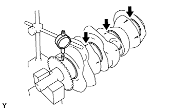
| 35. INSPECT CRANKSHAFT |
Inspect for circle runout.
Place the crankshaft on V-blocks.
Using a dial indicator, measure the circle runout at the center journal.
- Maximum circle runout:
- 0.06 mm (0.0024 in.)
 |
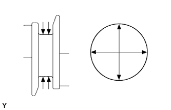
Inspect the main journals.
Using a micrometer, measure the diameter of each main journal.
- Standard journal diameter:
- 60.988 to 61.00 mm (2.4011 to 2.4016 in.)
Check each main journal for taper and out-of-round as shown in the illustration.
- Maximum taper and out-of-round:
- 0.02 mm (0.0008 in.)
 |
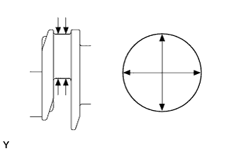
Inspect the crank pin.
Using a micrometer, measure the diameter of each crank pin.
- Standard crank pin diameter:
- 52.992 to 53.000 mm (2.0863 to 2.0866 in.)
Check each crank pin for taper and out-of-round as shown in the illustration.
- Maximum taper and out-of-round:
- 0.02 mm (0.0008 in.)
 |
| 36. INSPECT CRANKSHAFT BEARING CAP SET BOLT |
Using a vernier caliper, measure the minimum diameter of the compressed thread at the measuring point.
- Standard diameter:
- 10.8 to 11.0 mm (0.4252 to 0.4331 in.)
- Minimum diameter:
- 10.70 mm (0.4213 in.)
 |