Engine Unit -- Reassembly |
| 1. INSTALL PISTON |
Using a small screwdriver, install a new snap ring onto one end of the piston pin hole.
- HINT:
- Make sure that the end gap of the snap ring is not aligned with the pin hole cutout portion of the piston.
 |
Gradually heat the piston up to 80 to 90°C (176 to 194°F).
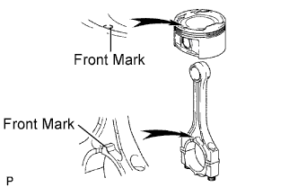
Align the front marks of the piston and connecting rod, then push in the piston pin with your thumb until the pin comes into contact with the snap pin hole.
- HINT:
- Make sure that the end gap of the snap ring is not aligned with the pin hole cutout portion of the piston.
 |
| 2. INSTALL PISTON RING SET |
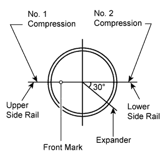
Install the expander and 2 side rails by hand.
Using a piston ring expander, install the 2 compression rings with the paint mark as shown in the illustration.
- NOTICE:
- Install the No. 2 compression ring with the code mark (T) facing upward.
 |
Position the piston rings so that the ring ends are as shown in the illustration.
 |
| 3. INSTALL CRANKSHAFT BEARING |
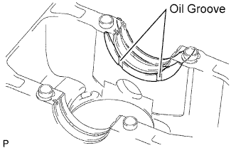
Install the upper bearing with an oil groove onto the cylinder block.
- NOTICE:
- Do not apply engine oil to the contact surfaces of the cylinder block and crankshaft bearing.
 |
| 4. INSTALL NO. 2 CRANKSHAFT BEARING |
Install the lower bearing onto the bearing cap.
- NOTICE:
- Do not apply engine oil to the contact surfaces of the cylinder block and crankshaft bearing cap.
 |
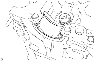
| 5. INSTALL CRANKSHAFT THRUST WASHER UPPER |
Install the 2 thrust washers onto the No. 3 journal position of the cylinder block with the oil groove facing outward.
 |
| 6. INSTALL CRANKSHAFT |
Apply engine oil to the upper bearing, and install the crankshaft onto the cylinder block.
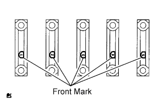
Examine the front marks and numbers, and install the bearing caps onto the cylinder block in the order shown in the illustration.
 |
Apply a light coat of engine oil to the threads and under the heads of the bearing cap bolts.
Using several steps, uniformly install and tighten the 10 bearing cap bolts in the sequence shown in the illustration.
- Torque:
- 40 N*m{408 kgf*cm, 30 ft.*lbf}
 |
Mark the front of the bearing cap bolts with paint.
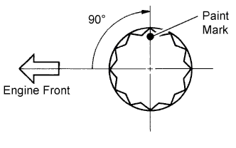 |
Retighten the 10 bearing cap bolts by 90° in the same sequence.
Check that the paint marks are now at a 90° angle to the front.
Check that the crankshaft turns smoothly.
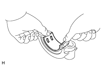
| 7. INSTALL CONNECTING ROD BEARING |
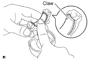
Align the bearing claw with the oil groove of the connecting rod or connecting rod cap.
- HINT:
- Do not apply engine oil to the contact surfaces of the connecting rod cap and bearing.
- Do not apply engine oil to the contact surfaces of the connecting rod and bearing.
 |
| 8. INSTALL PISTON WITH CONNECTING ROD |
Apply engine oil to the cylinder walls, pistons, and surfaces of connecting rod bearings.
Check the position of the piston ring ends.
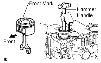
Using a hammer handle and piston ring compressor, press a piston and connecting rod assembly into each cylinder with the front mark of the piston facing forward.
 |
Check that the front mark of the connecting rod cap is facing in the correct direction.
- NOTICE:
- Match the numbered connecting rod cap with the connecting rod.
 |
Apply a light coat of engine oil to the threads and under the heads of the connecting rod bolts.
Using a 12 mm socket wrench, tighten the bolts in several passes to the specified torque.
- Torque:
- 24.5 N*m{250 kgf*cm, 18 ft.*lbf}
Mark the front of the connecting rod bolts with paint.
|
Retighten the cap bolts 90°as shown in the illustration.
Check that the crankshaft turns smoothly.
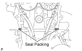
| 9. INSTALL STIFFENING CRANKCASE ASSEMBLY |
Remove any old packing material and be careful not to drop any oil on the contact surfaces of the cylinder block and crankcase.
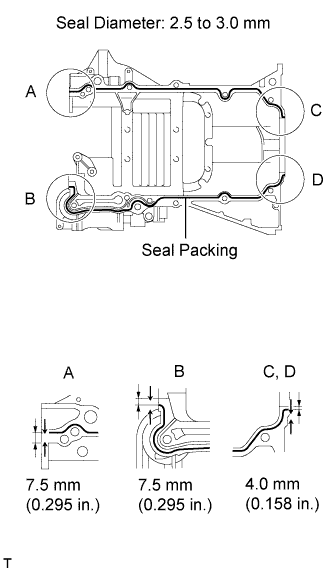
Apply a continuous bead of seal packing (Diameter 2.5 to 3.0 mm (0.098 to 0.118 in.)) as shown in the illustration.
- Seal packing:
- Toyota Genuine Seal Packing Black, Three Bond 1207B or Equivalent
- NOTICE:
- Remove any oil from the contact surface.
- Install the crankcase within 3 minutes of applying seal packing.
- Do not add engine oil for at least 2 hours after installing the crankcase.
 |
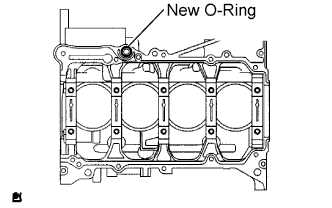
Place a new O-ring on the cylinder block as shown in the illustration.
 |
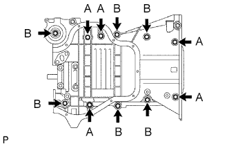
Temporarily install the crankcase with the 11 bolts.
Item Bolt Length Bolt A 112 mm (4.41 in.) Bolt B 35 mm (1.38 in.)
 |
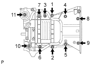
Uniformly tighten the bolts.
- Torque:
- 32.5 N*m{331 kgf*cm, 24 ft.*lbf}
 |
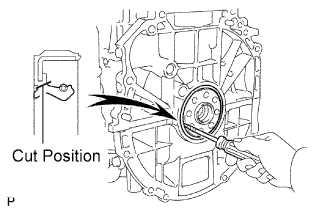
| 10. INSTALL ENGINE REAR OIL SEAL |
Using a knife, cut off the lip of the oil seal.
 |
Using a screwdriver with its tip wrapped with tape, pry out the oil seal.
- NOTICE:
- After removing, check the crankshaft for damage. If damaged, smooth the surface with 400-grit sandpaper.
Apply multi-purpose grease to the lip of a new oil seal.
- NOTICE:
- Keep the lip free of foreign objects.
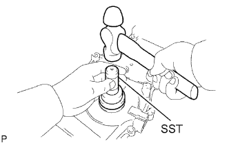
Using SST and a hammer, tap in the new oil seal until its surface is flush with the rear oil seal retainer edge.
- SST
- 09223-15030
09950-70010(09951-07100)
- NOTICE:
- Wipe any extra grease off the crankshaft.
 |
| 11. INSTALL NO. 1 TAPER SCREW PLUG (w/o Oil Cooler) |
Apply adhesive to 2 or 3 threads of the plug, and install it.
- Torque:
- 26 N*m{265 kgf*cm, 19 ft.*lbf}
- Adhesive:
- Toyota Genuine Adhesive 1324, Three Bond 1324 or Equivalent
- NOTICE:
- Install the plug within 3 minutes of applying adhesive.
- Do not add coolant for at least an hour after installing the plug.
 |
| 12. INSTALL OIL CONTROL VALVE FILTER |
Check that there are no foreign objects on the mesh part of the oil control valve filter.
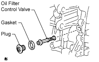 |
Using a 6 mm socket hexagon wrench, install a new gasket and the oil control valve filter with the plug.
- Torque:
- 30 N*m{306 kgf*cm, 22 ft.*lbf}
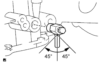
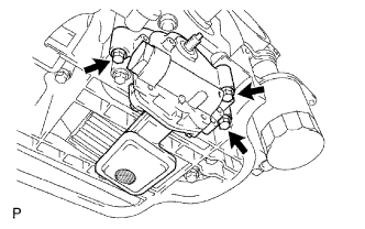
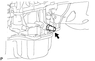
| 13. INSTALL CYLINDER BLOCK WATER DRAIN COCK SUB-ASSEMBLY |
Apply adhesive to 2 or 3 threads of the drain cock.
- Adhesive:
- Toyota Genuine Adhesive 1324, Three Bond 1324 or Equivalent
After tightening the drain cock to the specified torque, turn the drain cock clockwise as shown in the illustration.
- Torque:
- 25 N*m{255 kgf*cm, 18 ft.*lbf}
- NOTICE:
- Install the drain cock within 3 minutes of applying adhesive.
- Do not add coolant for at least an hour after installing the drain cock.
- Do not turn the drain cock by more than 1 revolution (360°) after tightening the drain cock to the specified torque.
- Do not loosen the drain cock after setting it correctly.
 |
| 14. INSTALL CYLINDER HEAD GASKET |
Place a new gasket on the cylinder block surface with the Lot No. stamp facing upward.
- NOTICE:
- Remove any oil from contact surface.
- Be careful of the installation direction.
 |
| 15. INSTALL CYLINDER HEAD SUB-ASSEMBLY |
Place the cylinder head on the head gasket.
- NOTICE:
- Place the cylinder head gently in order to avoid damaging the gasket.
Install the cylinder head bolts.
- NOTICE:
- The cylinder head bolts are tightened in 2 successive steps.
Apply a light coat of engine oil to the threads and under the heads of the cylinder head set bolts.
Using several steps, uniformly install and tighten the 10 cylinder head set bolts and plate washers with a 10 mm bi-hexagon wrench in the order shown in the illustration.
- Torque:
- 78.5 N*m{800 kgf*cm, 58 ft.*lbf}

Mark the front of the cylinder head bolts with paint.
 |
Retighten the cylinder head bolts by 90° as shown in the illustration.
Check that the paint mark is now at a 90° angle to the front.
| 16. INSTALL CAMSHAFT TIMING OIL CONTROL VALVE ASSEMBLY |
Apply a light coat of engine oil to the O-ring of the oil control valve.
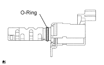 |
Install the oil control valve with the bolt.
- Torque:
- 9.0 N*m{92 kgf*cm, 80 in.*lbf}
- NOTICE:
- Make sure that the O-ring is not cracked or jammed.
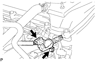 |
Connect the oil control valve connector.
| 17. INSTALL CAMSHAFT TIMING GEAR ASSEMBLY |
Put the camshaft timing gear and camshaft together with the straight pin and key groove misaligned, as shown in the illustration.
 |
Turn the camshaft timing gear as shown in the illustration while pushing it gently against the camshaft. Push further at the position where the pin fits into the groove.
- NOTICE:
- Be sure not to turn the camshaft timing gear to the retard angle side (the right angle).
Check that there is no clearance between the gear fringe and camshaft.
Tighten the flange bolt with the camshaft timing gear fixed in place.
- Torque:
- 54 N*m{551 kgf*cm, 40 ft.*lbf}
Check that the camshaft timing gear can move to the retard angle side (the right direction) and is locked in the most retarded position.
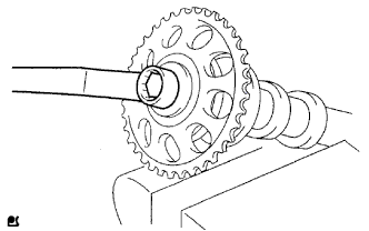
| 18. INSTALL NO. 2 CAMSHAFT TIMING SPROCKET |
Clamp the camshaft in a vise, then install the camshaft timing sprocket with the bolt.
- Torque:
- 54 N*m{551 kgf*cm, 40 ft.*lbf}
- NOTICE:
- Do not damage the camshaft.
 |
| 19. INSTALL NO. 2 CAMSHAFT BEARING |
Clean the contact surfaces of the bearing and the cylinder head.
- NOTICE:
- Do not apply engine oil to the contact surfaces of the camshaft bearing and cylinder block.
Install the No. 2 camshaft bearing onto the cylinder head.
 |
| 20. INSTALL NO. 1 CAMSHAFT BEARING |
Clean the contact surfaces of the bearing and the bearing cap.
- NOTICE:
- Do not apply engine oil to the contact surfaces of the camshaft bearing and bearing cap.
Align the bearing claw with the claw groove of No. 1 and No. 2 bearing cap, and push in the No. 1 camshaft bearing.
 |
| 21. INSTALL CAMSHAFT |
Apply a light coat of engine oil to the journal portion of the camshaft.
Place the 2 camshafts on the cylinder head with the No. 1 cam lobes facing the directions shown in the illustration.
 |
Examine the front marks and numbers, and check that the order is as shown in the illustration. Then install the bearing caps onto the cylinder head.
 |
Apply a light coat of engine oil to the threads and under the heads of the bearing cap bolts.
Using several steps, uniformly tighten the 20 bearing cap bolts in the sequence shown in the illustration.
- Torque:
- 29.5 N*m{301 kgf*cm, 22 ft.*lbf} for No. 1 and No. 2 bearing cap
- 9.0 N*m{92 kgf*cm, 80 in.*lbf} for No. 3 bearing cap
- NOTICE:
- Tighten the bolts after deciding the position in the thrust direction of the camshaft by the No. 1 and No. 2 bearing caps.
- Install the camshaft with the timing mark of the camshaft timing gear on top.
 |
| 22. INSTALL OIL PUMP DRIVE GEAR |
| 23. INSTALL OIL PUMP ASSEMBLY |
Install a new gasket and the oil pump with the 3 bolts.
- Torque:
- 19 N*m{194 kgf*cm, 14 ft.*lbf}
 |
| 24. INSTALL NO. 2 CHAIN SUB-ASSEMBLY |
Set the crankshaft key in the left horizontal position.
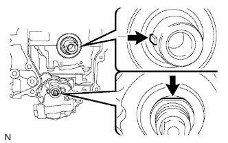 |
Turn the cutout of the drive shaft so that it faces upward.
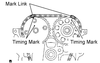
Align the yellow mark links with the timing marks of each gear as shown in the illustration.
 |
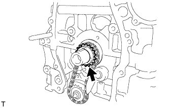
Install the sprockets onto the crankshaft and oil pump shaft with the chain wrapped on the gears.
Temporarily tighten the oil pump drive shaft sprocket with the nut.
Insert the damper spring into the adjusting hole, and then install the chain tensioner plate with the bolt.
- Torque:
- 12 N*m{122 kgf*cm, 9 ft.*lbf}
 |
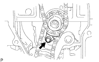
Align the adjusting hole of the oil pump drive shaft sprocket with the groove of the oil pump.
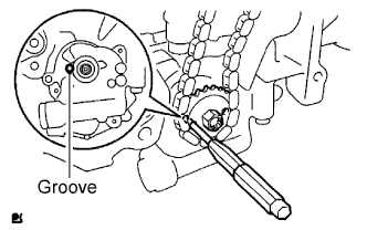 |
Insert a 4 mm diameter bar into the adjusting hole of the oil pump drive shaft gear to lock the gear in position, and then tighten the nut.
- Torque:
- 29.5 N*m{301 kgf*cm, 22 ft.*lbf}
| 25. INSTALL CRANKSHAFT TIMING SPROCKET |
 |
| 26. INSTALL NO. 1 CHAIN VIBRATION DAMPER |
Install the chain vibration damper with the 2 bolts.
- Torque:
- 9.0 N*m{92 kgf*cm, 80 in.*lbf}
 |
| 27. INSTALL CHAIN SUB-ASSEMBLY |
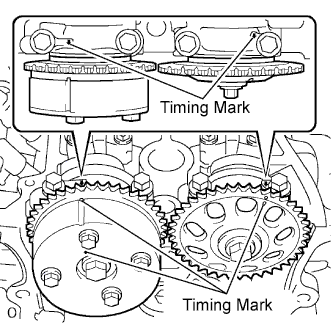
Set the No. 1 cylinder to TDC/compression.
Turn the camshafts with a wrench (using the hexagonal lobe) to align the timing marks of the camshaft timing gear with each timing mark located on the No. 1 and No. 2 bearing caps as shown in the illustration.
Using the crankshaft pulley bolt, turn the crankshaft to position the key on the crankshaft upward.
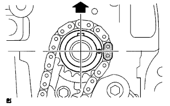
 |
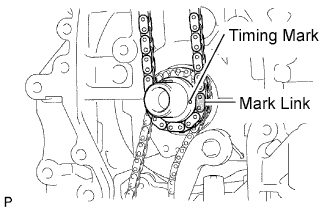
Install the chain onto the crankshaft timing sprocket with the gold or orange mark link aligned with the timing mark on the crankshaft.
 |
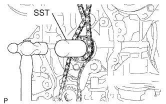
Using SST and a hammer, tap in the crankshaft timing sprocket.
- SST
- 09309-37010
 |
Align the gold or yellow links with each timing mark located on the camshaft timing gear and sprocket, then install the chain.
 |
| 28. INSTALL CHAIN TENSIONER SLIPPER |
Install the chain tensioner slipper with the bolt.
- Torque:
- 19 N*m{194 kgf*cm, 14 ft.*lbf}
 |
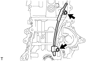
| 29. INSTALL TIMING CHAIN GUIDE |
Install the timing chain guide with the bolt.
- Torque:
- 9.0 N*m{92 kgf*cm, 80 in.*lbf}
 |
| 30. INSTALL NO. 1 CRANKSHAFT POSITION SENSOR PLATE |
Install the sensor plate with the "F" mark facing forward.
 |
| 31. INSTALL TIMING CHAIN COVER OIL SEAL |
Apply multi-purpose grease to the lip of a new oil seal.
- NOTICE:
- Keep the lip free of foreign objects.
Using SST and a hammer, tap in a new oil seal until its surface is flush with the timing gear case edge.
- SST
- 09223-22010
- NOTICE:
- Do not tap the oil seal at an angle.
 |
| 32. INSTALL TIMING CHAIN COVER SUB-ASSEMBLY |
Remove any old packing material and be careful not to drop any oil on the contact surfaces of the timing chain cover, cylinder head and cylinder block.
Apply seal packing (Diameter 4.0 to 4.5 mm (0.157 to 0.177 in.)) as shown in the illustration.
- Seal packing:
- Toyota Genuine Seal Packing Black, Three Bond 1207B or Equivalent
- NOTICE:
- Remove any oil from the contact surface.
- Install the chain cover within 3 minutes of applying seal packing.
- Do not add engine oil for at least 2 hours after installing the chain cover.
 |
Apply a continuous bead of seal packing as shown in the illustration.
- Seal packing:
- Toyota Genuine Seal Packing Black, Three Bond 1207B or Equivalent
- NOTICE:
- Remove any oil from the contact surface.
- Install the chain cover within 3 minutes of applying seal packing.
- Do not add engine oil for at least 2 hours after installing the chain cover.

Install the timing chain cover with the 11 bolts and 2 nuts.
- Torque:
- 9.0 N*m{92 kgf*cm, 80 in.*lbf} for bolt A
- 25 N*m{255 kgf*cm, 18 ft.*lbf} for bolt B
- 55 N*m{561 kgf*cm, 41 ft.*lbf} for bolt C
- 11 N*m{112 kgf*cm, 8 ft.*lbf} for nut
- HINT:
- Bolt length:
Bolt A 30 mm (1.18 in.) length for 10 mm head Bolt B 30 mm (1.18 in.) length for 12 mm head Bolt C 40 mm (1.57 in.) length for 14 mm head
 |
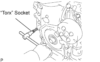
Using an E10 "torx" socket, install the stud bolt for the V-ribbed belt tensioner.
- Torque:
- 21.5 N*m{219 kgf*cm, 16 ft.*lbf}
 |
| 33. INSTALL NO. 1 CHAIN TENSIONER ASSEMBLY |
Release the ratchet pawl, then fully push in the plunger and hook the hook to the pin so that the plunger is in the position shown in the illustration.
 |
Install a new gasket and the chain tensioner with the 2 nuts.
- Torque:
- 9.0 N*m{92 kgf*cm, 80 in.*lbf}
- NOTICE:
- When installing the chain tensioner, set the hook again if the hook releases the plunger.
 |
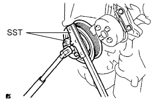
| 34. INSTALL CRANKSHAFT PULLEY |
Using SST, fix the pulley in place and tighten the bolt.
- SST
- 09213-54015(91651-60855)
09330-00021
- Torque:
- 180 N*m{1,835 kgf*cm, 133 ft.*lbf}
 |
Turn the crankshaft counterclockwise, then disconnect the plunger knock pin from the hook.
 |
Turn the crankshaft clockwise, then check that the plunger is extended.
 |
| 35. INSTALL OIL PAN SUB-ASSEMBLY |
Remove any old packing material and be careful not to drop any oil on the contact surfaces of the cylinder block and oil pan.
Apply a continuous bead of seal packing (Diameter 3.0 to 4.0 mm (0.118 to 0.157 in.)) as shown in the illustration.
- Seal packing:
- Toyota Genuine Seal Packing Black, Three Bond 1207B or Equivalent
- NOTICE:
- Remove any oil from the contact surface.
- Install the oil pan within 3 minutes of applying seal packing.
- Do not add engine oil for at least 2 hours after installing the oil pan.
 |
Install the oil pan to the cylinder block.
Uniformly tighten the 12 bolts and 2 nuts in the sequence shown in the illustration.
- Torque:
- 9.0 N*m{92 kgf*cm, 80 in.*lbf}
 |
Place a transmission jack underneath the engine, then put a wooden block on the jack.
 |
Remove the chain block and sling device.
Remove the No. 1 and No. 2 engine hangers.
| 36. INSTALL OIL PAN DRAIN PLUG |
Place a new gasket on the oil pan drain plug, then install it onto the oil pan.
- Torque:
- 40 N*m{408 kgf*cm, 30 ft.*lbf}
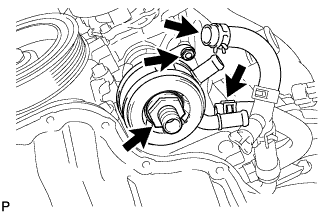
| 37. INSTALL WATER PUMP ASSEMBLY |
Remove any old seal packing material from the contact surface.
Apply a continuous line of seal packing as shown in the illustration.
- Seal packing:
- Toyota Genuine Seal Packing Black, Three Bond 1207B or Equivalent
- Standard seal diameter:
- 2.2 to 2.5 mm (0.09 to 0.10 in.)
- NOTICE:
- Remove any oil from the contact surface.
- The parts must be set within 3 minutes after applying seal packing. Otherwise, the material must be removed and reapplied.
 |
Install the water pump and clamp bracket with the 4 bolts and 2 nuts.
- Torque:
- 9.0 N*m{92 kgf*cm, 80 in.*lbf}
Install the wire of the crankshaft position sensor onto the clamp bracket.
Install the clamp of the crankshaft position sensor onto the water pump.
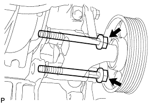
| 38. INSTALL WATER PUMP PULLEY |
 |
Using SST, install the water pump pulley with the 4 bolts.
- SST
- 09960-10010(09962-01000,09963-00700)
- Torque:
- 26 N*m{265 kgf*cm, 19 ft.*lbf}
| 39. INSTALL CRANKSHAFT POSITION SENSOR |
 |
- NOTICE:
- Make sure that the O-ring is not cracked or jammed when installing.
Apply a light coat of engine oil to the O-ring of the sensor.
Install the sensor with the bolt.
- Torque:
- 9.0 N*m{90 kgf*cm, 80 in.*lbf}
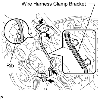 |
Install the wire harness clamp.
Install the connector clamp.
Connect the sensor connector.
Confirm that the wire harness of the sensor is secured to the wire harness clamp bracket through the back of the rib of the timing chain cover.
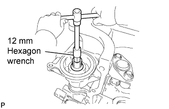
| 40. INSTALL OIL FILTER UNION (w/o Oil Cooler) |
Using a 12 mm hexagon wrench, install the oil filter union.
- Torque:
- 29.5 N*m{301 kgf*cm, 22 ft.*lbf}
 |
| 41. INSTALL OIL FILTER SUB-ASSEMBLY |
Check and clean the oil filter installation surface.
Apply clean engine oil to the gasket of a new oil filter.
Lightly screw the oil filter into place by hand. Tighten it until the gasket contacts the seat.
 |
Using SST, tighten the oil filter.
- SST
- 09228-06501
Depending on the work space available, choose from the following.
1. If enough space is available, use a torque wrench to tighten the oil filter.- Torque:
- 17.2 N*m{175 kgf*cm, 13 ft.*lbf}
| 42. SET NO. 1 CYLINDER TO TDC/COMPRESSION |
Turn the crankshaft pulley until its groove and the timing mark "0" of the timing chain cover are aligned.
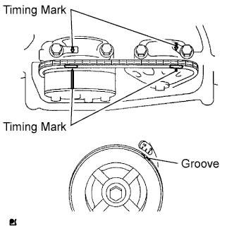 |
Check that each timing mark of the camshaft timing gear and sprocket is aligned with each timing mark located on the No. 1 and No. 2 bearing caps as shown in the illustration.
If not, turn the crankshaft by 1 revolution (360°) to align the timing marks as above.
| 43. CHECK VALVE CLEARANCE |
Check only the valves indicated.
Using a feeler gauge, measure the clearance between the valve lifter and camshaft.
- Standard valve clearance (cold):
Item Standard Condition Intake 0.21 to 0.27 mm (0.0083 to 0.0106 in.) Exhaust 0.30 to 0.40 mm (0.0118 to 0.0157 in.)
Record any out-of-specification valve clearance measurements. They will be used later to determine the required replacement valve clearance lifters.
 |
Turn the crankshaft 1 revolution (360°) and set the No. 4 cylinder to the TDC/compression.
Check only the valves indicated.
Using a feeler gauge, measure the clearance between the valve lifter and camshaft.
- Standard valve clearance (cold):
Item Standard Condition Intake 0.21 to 0.27 mm (0.0083 to 0.0106 in.) Exhaust 0.30 to 0.40 mm (0.0118 to 0.0157 in.)
Record any out-of-specification valve clearance measurements. They will be used later to determine the required replacement valve lifters.
 |
| 44. ADJUST VALVE CLEARANCE |
Remove the No. 2 camshaft (RAV4_ACA30 RM000001AN800TX_01_0057.html).
Remove the camshaft (RAV4_ACA30 RM000001AN800TX_01_0058.html).
Remove the valve lifters.
Using a micrometer, measure the thickness of the removed valve lifters.
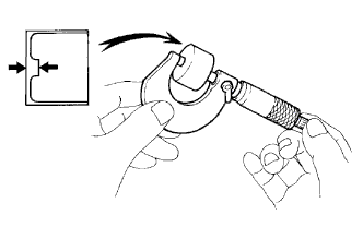 |
Calculate the thickness of a new lifter so that the valve clearance comes within the specified values.
- New lifter thickness:
Item Specification Intake A = B + (C - 0.24 mm (0.0095 in.)) Exhaust A = B + (C - 0.35 mm (0.0138 in.))
EXAMPLE (Intake):A New lifter thickness B Used lifter thickness C Measured valve clearance - Measured intake valve clearance = 0.16 mm (0.0063 in.)
(Measured - Specification = Excess clearance) - 0.40 mm (0.0158 in.) - 0.24 mm (0.0095 in.) = 0.16 mm (0.0063 in.)
- Measured used lifter measurement = 5.250 mm (0.2067 in.)
- New lifter thickness = 5.410 mm (0.2130 in.)
(Excess clearance + Used lifter thickness = Ideal new lifter) - 0.16 mm (0.0063 in.) + 5.250 mm (0.2067 in.) = 5.410 mm (0.2130 in.)
- Closest new lifter = 5.420 mm (0.2134 in.)
- Select No. 42 lifter
Select a new lifter with a thickness as close as possible to the calculated values.
- HINT:
- Lifters are available in 35 sizes in increments of 0.020 mm (0.0008 in.), from 5.060 to 5.740 mm (0.1992 to 0.2260 in.).)
The identification number inside the valve lifters shows the value to 2 decimal places. (The illustration shows 5.420 mm (0.2134 in.)
Valve lifter selection chart (intake).

New lifter thickness Lifter No. Thickness
mm (in.)Lifter No. Thickness
mm (in.)Lifter No. Thickness
mm (in.)06 5.060 (0.1992) 30 5.300 (0.2087) 54 5.540 (0.2181) 08 5.080 (0.2000) 32 5.320 (0.2094) 56 5.560 (0.2189) 10 5.100 (0.2008) 34 5.340 (0.2102) 58 5.580 (0.2197) 12 5.120 (0.2016) 36 5.360 (0.2110) 60 5.600 (0.2205) 14 5.140 (0.2024) 38 5.380 (0.2118) 62 5.620 (0.2213) 16 5.160 (0.2031) 40 5.400 (0.2126) 64 5.640 (0.2220) 18 5.180 (0.2039) 42 5.420 (0.2134) 66 5.660 (0.2228) 20 5.200 (0.2047) 44 5.440 (0.2142) 68 5.680 (0.2236) 22 5.220 (0.2055) 46 5.460 (0.2150) 70 5.700 (0.2244) 24 5.240 (0.2063) 48 5.480 (0.2157) 72 5.720 (0.2252) 26 5.260 (0.2071) 50 5.500 (0.2165) 74 5.740 (0.2260) 28 5.280 (0.2079) 52 5.520 (0.2173) - - - Standard intake valve clearance (cold):
- 0.21 to 0.27 mm (0.0083 to 0.0106 in.)
The 5.250 mm (0.2067 in.) lifter is installed, and the measured clearance is 0.400 mm (0.0157 in.). Replace the 5.250 mm (0.2067 in.) lifter with a new No. 42 lifter.
Valve lifter selection chart (Exhaust).

New lifter thickness Lifter No. Thickness
mm (in.)Lifter No. Thickness
mm (in.)Lifter No. Thickness
mm (in.)06 5.060 (0.1992) 30 5.300 (0.2087) 54 5.540 (0.2181) 08 5.080 (0.2000) 32 5.320 (0.2094) 56 5.560 (0.2189) 10 5.100 (0.2008) 34 5.340 (0.2102) 58 5.580 (0.2197) 12 5.120 (0.2016) 36 5.360 (0.2110) 60 5.600 (0.2205) 14 5.140 (0.2024) 38 5.380 (0.2118) 62 5.620 (0.2213) 16 5.160 (0.2031) 40 5.400 (0.2126) 64 5.640 (0.2220) 18 5.180 (0.2039) 42 5.420 (0.2134) 66 5.660 (0.2228) 20 5.200 (0.2047) 44 5.440 (0.2142) 68 5.680 (0.2236) 22 5.220 (0.2055) 46 5.460 (0.2150) 70 5.700 (0.2244) 24 5.240 (0.2063) 48 5.480 (0.2157) 72 5.720 (0.2252) 26 5.260 (0.2071) 50 5.500 (0.2165) 74 5.740 (0.2260) 28 5.280 (0.2079) 52 5.520 (0.2173) - - - Standard exhaust valve clearance (cold):
- 0.32 to 0.38 mm (0.0126 to 0.0150 in.)
The 5.340 mm (0.2102 in.) lifter is installed, and the measured clearance is 0.430 mm (0.0169 in.). Replace the 5.340 mm (0.2102 in.) lifter with a new No. 42 lifter.
Install the selected valve lifter.
| 45. INSTALL CAMSHAFT |
Apply a light coat of engine oil to the journal portion of the camshaft.
Place the 2 camshafts on the cylinder head with the No. 1 cam lobes facing the directions shown in the illustration.
|
Examine the front marks and numbers, and check that the order is as shown in the illustration. Then install the bearing caps onto the cylinder head.
|
Apply a light coat of engine oil to the threads and under the heads of the bearing cap bolts.
Using several steps, uniformly tighten the 20 bearing cap bolts in the sequence shown in the illustration.
- Torque:
- 29.5 N*m{301 kgf*cm, 22 ft.*lbf} for No. 1 and No. 2 bearing cap
- 9.0 N*m{92 kgf*cm, 80 in.*lbf} for No. 3 bearing cap
- NOTICE:
- Tighten the bolts after deciding the position in the thrust direction of the camshaft by the No. 1 and No. 2 bearing caps.
- Install the camshaft with the timing mark of the camshaft timing gear on top.
|
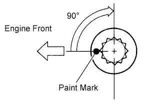
| 46. INSTALL NO. 2 CAMSHAFT |
Apply a light coat of engine oil to the journal portion of the No. 2 camshaft.
Put the No. 2 camshaft on the cylinder head with the paint mark of the chain aligned with the timing mark on the camshaft timing sprocket.
 |
While holding the No. 2 camshaft by hand, temporarily tighten the camshaft timing sprocket set bolt.
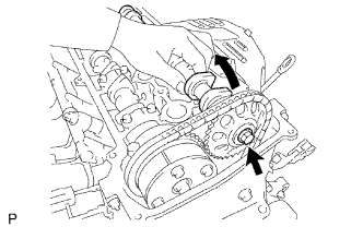 |
Examine the front marks and numbers, and check that the order is as shown in the illustration. Then install the bearing caps onto the cylinder head.
 |
Apply a light coat of engine oil to the threads and under the heads of the bearing cap bolts.
Using several steps, uniformly tighten the 10 bearing cap bolts in the sequence shown in the illustration.
- Torque:
- 29.5 N*m{301 kgf*cm, 22 ft.*lbf} for No. 2 bearing cap
- 9.0 N*m{92 kgf*cm, 80 in.*lbf} for No. 3 bearing cap
 |
While holding the camshaft with a wrench, tighten the camshaft timing sprocket set bolt.
- Torque:
- 54 N*m{551 kgf*cm, 40 ft.*lbf}
- NOTICE:
- Be careful not to damage the valve lifter.
 |
Check that the paint marks on the chain are aligned with the timing marks on the camshaft timing gear and camshaft timing sprocket. Also, check that the crankshaft pulley groove is aligned with the timing mark "0" of the timing chain cover.
 |
| 47. INSTALL NO. 1 CHAIN TENSIONER ASSEMBLY |
Release the ratchet pawl, then fully push in the plunger and hook the hook to the pin so that the plunger is in the position shown in the illustration.
|
Install a new gasket and the chain tensioner with the 2 nuts.
- Torque:
- 9.0 N*m{92 kgf*cm, 80 in.*lbf}
- NOTICE:
- When installing the chain tensioner, set the hook again if the hook releases the plunger.
|
| 48. INSTALL CYLINDER HEAD COVER GASKET |
Install the gasket onto the cylinder head cover.
 |
| 49. INSTALL CYLINDER HEAD COVER SUB-ASSEMBLY |
Remove any old packing material from the contact surface.
Apply seal packing to the 2 locations shown in the illustration.
- Seal packing:
- Toyota Genuine Seal Packing Black, Three Bond 1207B or Equivalent
- NOTICE:
- Remove any oil from the contact surface.
- Install the oil pan within 3 minutes of applying seal packing.
- Do not add engine oil for at least 2 hours after installing the oil pan.
 |
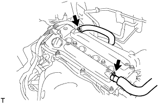
Install the cylinder head cover with the 8 bolts and 2 nuts.
- Torque:
- 11 N*m{112 kgf*cm, 8 ft.*lbf} for bolt A
- 14 N*m{143 kgf*cm, 10 ft.*lbf} for bolt B
- 11 N*m{112 kgf*cm, 8 ft.*lbf} for nut
 |
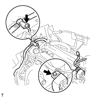
Install the 2 engine wires with the 2 bolts.
- Torque:
- 8.4 N*m{86 kgf*cm, 74 in.*lbf}
 |
Connect the 2 ventilation hoses to the cylinder head cover.
 |
| 50. INSTALL SPARK PLUG |
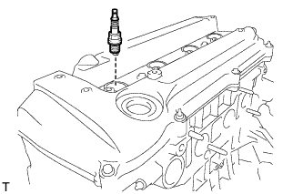 |
- Torque:
- 25 N*m{254 kgf*cm, 18 ft.*lbf}
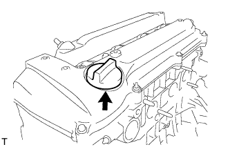
| 51. INSTALL OIL FILLER CAP SUB-ASSEMBLY |
Install the gasket to the cap.
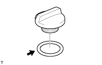 |
Install the oil filler cap.
- Torque:
- 3.0 N*m{31 kgf*cm, 26 in.*lbf}
 |
| 52. INSTALL IGNITION COIL ASSEMBLY |
Install the 4 ignition coils with the 4 bolts.
- Torque:
- 9.0 N*m{92 kgf*cm, 80 in.*lbf}
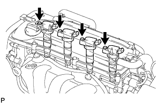 |
Connect the 4 ignition coil connectors.
| 53. INSTALL VENTILATION VALVE SUB-ASSEMBLY |
Apply adhesive to 2 or 3 threads of the ventilation valve.
- Adhesive:
- Toyota Genuine Adhesive 1324, Three Bond 1324 or Equivalent
 |
Using a 22 mm deep socket wrench, install the ventilation valve.
- Torque:
- 19 N*m{194 kgf*cm, 14 ft.*lbf}
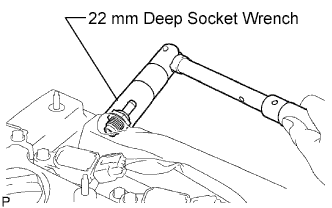 |
Connect the ventilation hose.
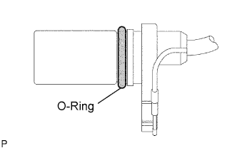
| 54. INSTALL OIL DIPSTICK GUIDE |
Apply a light coat of engine oil to a new O-ring and install it onto the guide.
Install the guide with the bolt.
- Torque:
- 9.0 N*m{92 kgf*cm, 80 in.*lbf}
 |
| 55. INSTALL OIL DIPSTICK |
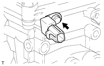
| 56. INSTALL CAMSHAFT POSITION SENSOR |
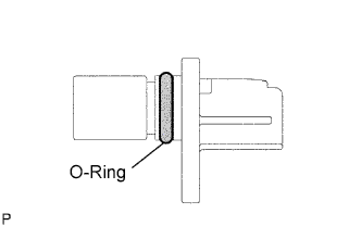 |
- NOTICE:
- Make sure that the O-ring is not cracked or jammed when installing.
Apply a light coat of engine oil to the O-ring of the sensor.
Install the sensor with the bolt.
- Torque:
- 9.0 N*m{90 kgf*cm, 80 in.*lbf}
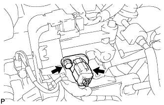 |
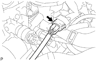
Connect the sensor connector.
| 57. INSTALL ENGINE COOLANT TEMPERATURE SENSOR |
Install a new gasket onto the sensor.
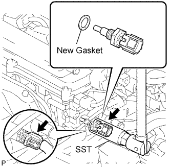 |
Using SST, install the sensor.
- SST
- 09817-33190
- Torque:
- 19.6 N*m{200 kgf*cm, 14 ft.*lbf}
Connect the sensor connector.
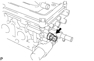
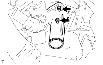
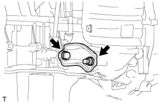
| 58. INSTALL ENGINE OIL PRESSURE SWITCH ASSEMBLY |
Apply adhesive to 2 or 3 threads of the oil pressure switch.
- Adhesive:
- Toyota Genuine Adhesive 1344, Three Bond 1344 or Equivalent
Install the oil pressure switch.
- Torque:
- 13 N*m{133 kgf*cm, 10 ft.*lbf}
 |
| 59. INSTALL RADIO SETTING CONDENSER |
Install the condenser with the bolt.
- Torque:
- 10 N*m{102 kgf*cm, 7 ft.*lbf}
 |
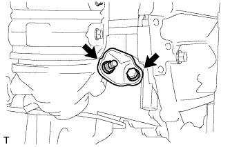
| 60. INSTALL KNOCK SENSOR |
Install the sensor with the nut.
- Torque:
- 20 N*m{205 kgf*cm, 15 ft.*lbf}
- NOTICE:
- Make sure that the knock sensor is in the correct position.
 |
Connect the sensor connector.
| 61. INSTALL CAMSHAFT TIMING OIL CONTROL VALVE ASSEMBLY |
Apply a light coat of engine oil to the O-ring of the oil control valve.
|
Install the oil control valve with the bolt.
- Torque:
- 9.0 N*m{92 kgf*cm, 80 in.*lbf}
- NOTICE:
- Make sure that the O-ring is not cracked or jammed.
|
Connect the oil control valve connector.
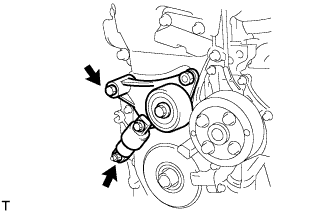
| 62. INSTALL V-RIBBED BELT TENSIONER ASSEMBLY |
Install the V-ribbed belt tensioner with the bolt and nut.
- Torque:
- 59.5 N*m{607 kgf*cm, 44 ft.*lbf}
- NOTICE:
- Do not lift the engine more than necessary.
 |
| 63. INSTALL ENGINE OIL COOLER (w/ Oil Cooler) |
Clean the oil cooler contact surface on the cooler mounting.
Install a new O-ring to the oil cooler.
 |
Apply a light coat of engine oil on the threads and under the head of the union bolt.
Install the oil cooler with the plate washer, nut and union bolt.
- Torque:
- 68.6 N*m{700 kgf*cm, 51 ft.*lbf} for union bolt
- 9.0 N*m{92 kgf*cm, 80 in.*lbf} for nut
 |
Connect the 2 oil cooler hoses.
| 64. INSTALL OIL FILTER SUB-ASSEMBLY |
Check and clean the oil filter installation surface.
Apply clean engine oil to the gasket of a new oil filter.
Lightly screw the oil filter into place by hand. Tighten it until the gasket contacts the seat.
|
Using SST, tighten the oil filter.
- SST
- 09228-06501
Depending on the work space available, choose from the following.
1. If enough space is available, use a torque wrench to tighten the oil filter.- Torque:
- 17.2 N*m{175 kgf*cm, 13 ft.*lbf}
| 65. INSTALL OIL COOLER PIPE (w/ ATF WARMER) |
Install a new gasket and the pipe with the bolt and 2 nuts.
- Torque:
- 9.0 N*m{92 kgf*cm, 80 in.*lbf}
 |
| 66. INSTALL UNION BOLT (w/ Oil Cooler) |
Apply adhesive to the threads of the union bolt.
- Adhesive:
- Toyota Genuine Adhesive 1324, Three Bond 1324 or Equivalent
Install the union bolt.
- Torque:
- 25 N*m{255 kgf*cm, 18 ft.*lbf}
 |
| 67. INSTALL NO. 3 WATER BY-PASS PIPE (w/ Oil Cooler) |
Install a new gasket and pipe with the bolt and 2 nuts.
- Torque:
- 9.0 N*m{92 kgf*cm, 80 in.*lbf}
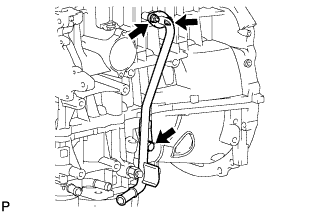 |
Connect the No. 3 and No. 4 water by-pass hoses to the oil cooler.
 |
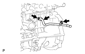
| 68. INSTALL NO. 1 WATER BY-PASS PIPE (w/o Oil Cooler) |
Install a new gasket and the pipe with the bolt and 2 nuts.
- Torque:
- 9.0 N*m{92 kgf*cm, 80 in.*lbf}
 |
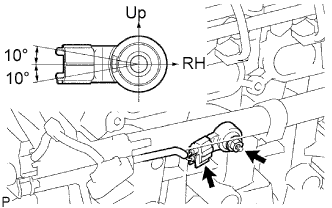
| 69. INSTALL THERMOSTAT |
Install a new gasket onto the thermostat.
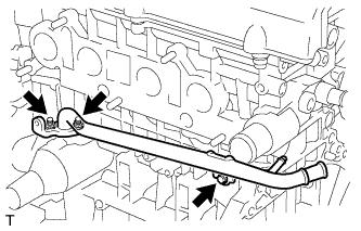
Install the thermostat with the jiggle valve upward.
- HINT:
- The jiggle valve may be set to within 10° on either side of the prescribed position.
 |
| 70. INSTALL WATER INLET |
Install the water inlet with the 2 nuts.
- Torque:
- 9.0 N*m{92 kgf*cm, 80 in.*lbf}
 |
| 71. INSTALL EXHAUST MANIFOLD CONVERTER SUB-ASSEMBLY |
Install a new gasket onto the cylinder head.
Temporarily tighten the exhaust manifold converter with the 5 nuts.
Tighten the 5 nuts in the sequence shown in the illustration.
- Torque:
- 37 N*m{377 kgf*cm, 27 ft.*lbf}
 |
| 72. INSTALL NO. 1 EXHAUST MANIFOLD HEAT INSULATOR |
Install the exhaust manifold heat insulator with the 4 bolts.
- Torque:
- 12 N*m{122 kgf*cm, 9 ft.*lbf}
 |
Connect the air-fuel ratio sensor connector.
 |
| 73. INSTALL NO. 2 MANIFOLD STAY |
Install the stay with the bolt and nut.
- Torque:
- 44 N*m{449 kgf*cm, 32 ft.*lbf}
 |
| 74. INSTALL MANIFOLD STAY |
Install the stay with the bolt and nut.
- Torque:
- 44 N*m{449 kgf*cm, 32 ft.*lbf}
 |
| 75. INSTALL IDLER PULLEY BRACKET |
Install the bracket with the 2 bolts.
- Torque:
- 60 N*m{612 kgf*cm, 44 ft.*lbf}
 |