Dtc P2102 Throttle Actuator Control Motor Circuit Low
Engine. Toyota Rav4. Aca30, 33, 38 Gsa33 Zsa30, 35
DESCRIPTION
FAIL-SAFE
WIRING DIAGRAM
INSPECTION PROCEDURE
INSPECT THROTTLE BODY ASSEMBLY (RESISTANCE OF THROTTLE ACTUATOR)
CHECK HARNESS AND CONNECTOR (THROTTLE ACTUATOR - ECM)
INSPECT THROTTLE BODY (VISUALLY CHECK THROTTLE VALVE)
CHECK THROTTLE BODY (THROTTLE VALVE)
DTC P2102 Throttle Actuator Control Motor Circuit Low |
DTC P2103 Throttle Actuator Control Motor Circuit High |
DESCRIPTION
The throttle actuator is operated by the ECM and opens and closes the throttle valve using gears.The opening angle of the throttle valve is detected by the throttle position sensor, which is built into the throttle body assembly. The throttle position sensor provides feedback to the ECM. This feedback allows the ECM to appropriately control the throttle actuator and monitor the throttle valve opening angle as the ECM responds to driver inputs. - HINT:
- This electronic throttle control system does not use a throttle cable.
DTC No.
| DTC Detection Condition
| Trouble Area
|
P2102
| Conditions (a) and (b) continue for 2.0 seconds (1 trip detection logic):
(a) The throttle actuator duty ratio is 80% or more.
(b) The throttle actuator current is 0.5 A or less.
| - Open in throttle actuator circuit
- Throttle actuator
- ECM
|
P2103
| Either condition is met (1 trip detection logic):
- The throttle actuator current is 10 A or higher for 0.1 seconds.
- The throttle actuator current is 7 A or higher for 0.6 seconds.
| - Short in throttle actuator circuit
- Throttle actuator
- Throttle valve
- Throttle body assembly
- ECM
|
FAIL-SAFE
When either of these DTCs, or other DTCs relating to electronic throttle control system malfunctions, is stored, the ECM enters fail-safe mode. During fail-safe mode, the ECM cuts the current to the throttle actuator, and the throttle valve is returned to a 5.5° opening angle by the return spring. The ECM then adjusts the engine output by controlling the fuel injection (intermittent fuel-cut) and ignition timing, in accordance with the accelerator pedal position, to allow the vehicle to continue at a minimal speed. If the accelerator pedal is depressed gently, the vehicle can be driven slowly. Fail-safe mode continues until a pass condition is detected and the ignition switch is turned off.
WIRING DIAGRAM
INSPECTION PROCEDURE
- HINT:
- Read freeze frame data using the intelligent tester. The ECM records vehicle and driving condition information as freeze frame data the moment a DTC is stored. When troubleshooting, freeze frame data can help determine if the vehicle was moving or stationary, if the engine was warmed up or not, if the air fuel ratio was lean or rich, and other data from the time the malfunction occurred.
- The throttle actuator current (Throttle Motor Current) and throttle actuator duty ratio (Throttle Motor Open Duty / Throttle Motor Close Duty) can be read using the intelligent tester. However, the ECM shuts off the throttle actuator current when the electronic throttle control system malfunctions.
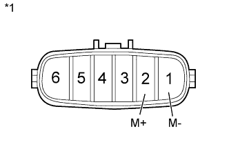
| 1.INSPECT THROTTLE BODY ASSEMBLY (RESISTANCE OF THROTTLE ACTUATOR) |
Disconnect the throttle body assembly connector.
Measure the resistance according to the value(s) in the table below.
- Standard Resistance:
Tester Connection
| Condition
| Specified Condition
|
2 (M+) - 1 (M-)
| 20°C (68°F)
| 0.3 to 100 Ω
|
Text in Illustration*1
| Component without harness connected
(Throttle Body)
|
Reconnect the throttle body assembly connector.
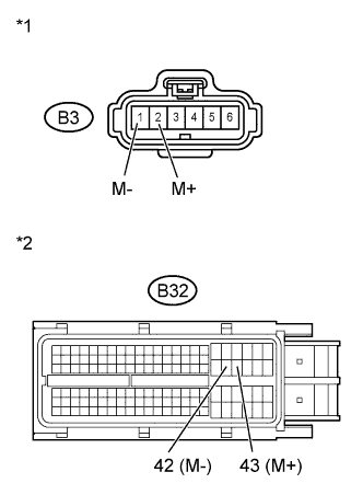
| 2.CHECK HARNESS AND CONNECTOR (THROTTLE ACTUATOR - ECM) |
Disconnect the throttle body assembly connector.
Disconnect the ECM connector.
Measure the resistance according to the value(s) in the table below.
- Standard Resistance (Check for Open):
Tester Connection
| Condition
| Specified Condition
|
B3-2 (M+) - B32-43 (M+)
| Always
| Below 1 Ω
|
B3-1 (M-) - B32-42 (M-)
| Always
| Below 1 Ω
|
- Standard Resistance (Check for Short):
Tester Connection
| Condition
| Specified Condition
|
B3-2 (M+) or B32-43 (M+) - Body ground
| Always
| 10 kΩ or higher
|
B3-1 (M-) or B32-42 (M-) - Body ground
| Always
| 10 kΩ or higher
|
Text in Illustration*1
| Front view of wire harness connector
(to Throttle Body)
|
*2
| Front view of wire harness connector
(to ECM)
|
Reconnect the throttle body assembly connector.
Reconnect the ECM connector.
| | REPAIR OR REPLACE HARNESS OR CONNECTOR (THROTTLE ACTUATOR - ECM) |
|
|
| 3.INSPECT THROTTLE BODY (VISUALLY CHECK THROTTLE VALVE) |
Check for foreign objects between the throttle valve and housing.
- OK:
- No foreign objects between throttle valve and housing.
| | REMOVE FOREIGN OBJECTS AND CLEAN THROTTLE BODY |
|
|
| 4.CHECK THROTTLE BODY (THROTTLE VALVE) |
Check if the throttle valve opens and closes smoothly.
- OK:
- Throttle valve opens and closes smoothly.