Dtc P1550 Battery Current Sensor Circuit
Engine. Toyota Rav4. Aca30, 33, 38 Gsa33 Zsa30, 35
DESCRIPTION
WIRING DIAGRAM
INSPECTION PROCEDURE
INSPECT BATTERY CURRENT SENSOR ASSEMBLY
CHECK HARNESS AND CONNECTOR (BATTERY CURRENT SENSOR - ECM)
DTC P1550 Battery Current Sensor Circuit |
DTC P1551 Battery Current Sensor Circuit Low |
DTC P1552 Battery Current Sensor Circuit High |
DESCRIPTION
 The battery current sensor installed on the negative (-) battery terminal detects the amount of current supplied from the generator.The battery current sensor changes current to voltage (at the negative (-) battery terminal) and sends it to the ECM. The ECM controls the voltage of the generator based on the signals from the battery current sensor.
DTC No.
| DTC Detection Condition
| Trouble Area
|
P1550
| The following condition continues for 10 seconds or more with the ignition switch to the ON position
(1 trip detection logic):
- Difference between the maximum and minimum current values of the battery current sensor is 1 A or less
| - Open or short in battery current sensor circuit
- Battery current sensor assembly
- ECM
|
P1551
| Battery current sensor output value is 0.2 V or less for 0.5 seconds or more with the ignition switch to the ON position
(1 trip detection logic):
| - Short in battery current sensor circuit
- Battery current sensor assembly
- ECM
|
P1552
| Battery current sensor output value is 4.8 V or more for 0.5 seconds or more with the ignition switch to the ON position
(1 trip detection logic):
| - Open in battery current sensor circuit
- Battery current sensor assembly
- ECM
|
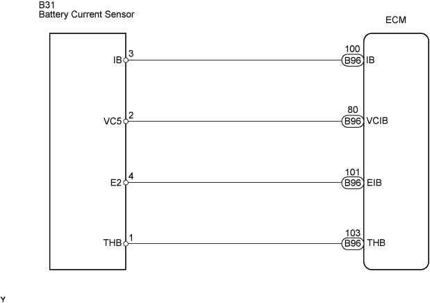
WIRING DIAGRAM
INSPECTION PROCEDURE
- HINT:
- Read freeze frame data using the intelligent tester. The ECM records vehicle and driving condition information as freeze frame data the moment a DTC is stored. When troubleshooting, freeze frame data can be helpful in determining whether the vehicle was running or stopped, whether the engine was warmed up or not, whether the air-fuel ratio was lean or rich, as well as other data recorded at the time of a malfunction (RAV4_ACA30 RM000000PDS09FX.html).
| 1.INSPECT BATTERY CURRENT SENSOR ASSEMBLY |
Disconnect the battery current sensor connector.
Measure the resistance of the battery current sensor.
- Standard resistance:
Tester Connection
| Specified Condition
|
VC5 (2) - E2 (4)
| 0.1 to 10 kΩ
|
VC5 (2) - IB (3)
| Below 0.5 kΩ
|
IB (3) - E2 (4)
| 0.05 to 10 kΩ
|
| | REPLACE BATTERY CURRENT SENSOR ASSEMBLY |
|
|
| 2.CHECK HARNESS AND CONNECTOR (BATTERY CURRENT SENSOR - ECM) |
Disconnect the battery current sensor connector.
Disconnect the ECM connectors.
Measure the resistance of the wire harness side connectors.
- Standard resistance (Check for open):
Tester Connection
| Specified Condition
|
IB (B31-3) - IB (B96-100)
| Below 1 Ω
|
VC5 (B31-2) - VCIB (B96-80)
| Below 1 Ω
|
E2 (B31-4) - EIB (B96-101)
| Below 1 Ω
|
THB (B31-1) - THB (B96-103)
| Below 1 Ω
|
- Standard resistance (Check for short):
Tester Connection
| Specified Condition
|
IB (B31-3) or IB (B96-100) - Body ground
| 10 kΩ or higher
|
VC5 (B31-2) or VCIB (B96-80) - Body ground
| 10 kΩ or higher
|
THB (B31-1) or THB (B96-103) - Body ground
| 10 kΩ or higher
|
| | REPAIR OR REPLACE HARNESS OR CONNECTOR |
|
|