Dtc P0500 Vehicle Speed Sensor A
Engine. Toyota Rav4. Aca30, 33, 38 Gsa33 Zsa30, 35
DESCRIPTION
WIRING DIAGRAM
INSPECTION PROCEDURE
CHECK OPERATION OF SPEEDOMETER
READ VALUE USING INTELLIGENT TESTER (VEHICLE SPEED)
CHECK COMBINATION METER ASSEMBLY (+S VOLTAGE)
CHECK COMBINATION METER ASSEMBLY (SPD SIGNAL WAVEFORM)
CHECK HARNESS AND CONNECTOR (COMBINATION METER ASSEMBLY - ECM)
DTC P0500 Vehicle Speed Sensor "A" |
DESCRIPTION
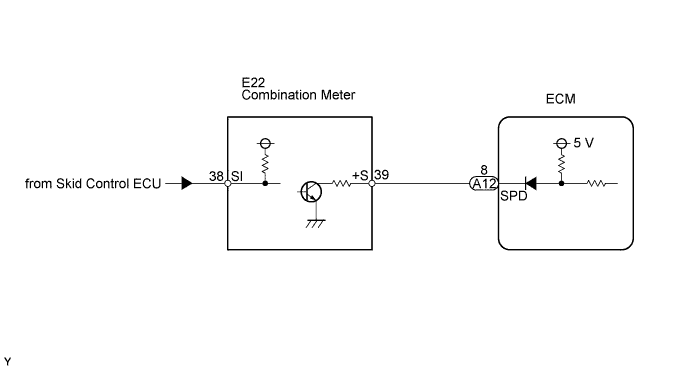
The wheel speed sensor monitors the wheel rotation speed and sends a signal to the skid control ECU. The skid control ECU converts the wheel speed signal into a 4-pulse signal and transmits it to the ECM via the combination meter. The ECM determines the vehicle speed based on the frequency of the pulse signal.- HINT:
- A voltage of 12 V or 5 V is output from each ECU and then input to the combination meter. The signal is changed to a pulse signal at the transistor in the combination meter. Each ECU controls the respective system based on the pulse signal.
- If a short occurs in any of the ECUs or in the wire harness connected to an ECU, all systems in the diagram below will not operate normally.
DTC No.
| DTC Detection Condition
| Trouble Area
|
P0500
| While vehicle being driven, no vehicle speed sensor signal to ECM.
(1 trip detection logic)
| - Open or short in speed signal circuit
- Combination meter
- Skid control ECU
- ECM
|
WIRING DIAGRAM
INSPECTION PROCEDURE
- HINT:
- Read freeze frame data using the intelligent tester. The ECM records vehicle and driving condition information as freeze frame data the moment a DTC is stored. When troubleshooting, freeze frame data can help determine if the vehicle was moving or stationary, if the engine was warmed up or not, if the air-fuel ratio was lean or rich, and other data from the time the malfunction occurred.
| 1.CHECK OPERATION OF SPEEDOMETER |
Drive the vehicle and check whether the operation of the speedometer in the combination meter is normal.
- HINT:
- The vehicle speed sensor is operating normally if the speedometer reading is normal.
- If the speedometer does not operate, check it by following the procedure described in speedometer malfunction (RAV4_ACA30 RM0000020T6002X.html).
| | GO TO MALFUNCTION IN SPEEDOMETER |
|
|
| 2.READ VALUE USING INTELLIGENT TESTER (VEHICLE SPEED) |
Connect the intelligent tester to the DLC3.
Turn the ignition switch to the ON position and turn the tester on.
Select the following menu items: Powertrain / Engine and ECT / Data List / Vehicle Speed.
Drive the vehicle.
Read the value displayed on the tester.
- OK:
- Vehicle speeds displayed on tester and speedometer display are equal.
| 3.CHECK COMBINATION METER ASSEMBLY (+S VOLTAGE) |
Disconnect the combination meter connector.
Turn the ignition switch to the ON position.
Measure the voltage between the terminal of the combination meter and the body ground.
- Standard voltage:
Tester Connection
| Specified Condition
|
+S (E22-39) - Body ground
| 9 to 14 V
|
Reconnect the combination meter connector.
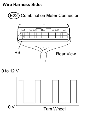
| 4.CHECK COMBINATION METER ASSEMBLY (SPD SIGNAL WAVEFORM) |
Shift the transmission gear selector lever to the neutral position.
Jack up the vehicle.
Turn the ignition switch to the ON position.
Measure the voltage between the terminal of the combination meter and the body ground while the front wheel is turned slowly.
- Standard voltage:
Tester Connection
| Specified Condition
|
+S (E22-39) - Body ground
| Voltage generated intermittently
|
- HINT:
- The output voltage should fluctuate up and down, similarly to the diagram, when the wheel is turned slowly.
| | REPLACE COMBINATION METER ASSEMBLY |
|
|
| 5.CHECK HARNESS AND CONNECTOR (COMBINATION METER ASSEMBLY - ECM) |
Disconnect the combination meter connector.
Disconnect the ECM connector.
Measure the resistance.
- Standard resistance (check for open):
Tester Connection
| Specified Condition
|
+S (E22-39) - SPD (A12-8)
| Below 1 Ω
|
- Standard resistance (check for short):
Tester Connection
| Specified Condition
|
+S (E22-39) or SPD (A12-8) - Body ground
| 10 kΩ or higher
|
Reconnect the combination meter connector.
Reconnect the ECM connector.
| | REPAIR OR REPLACE HARNESS OR CONNECTOR |
|
|