Engine. Toyota Rav4. Aca30, 33, 38 Gsa33 Zsa30, 35
1Az-Fe Engine Control System. Toyota Rav4. Aca30, 33, 38 Gsa33 Zsa30, 35
Sfi System -- Freeze Frame Data |
| DESCRIPTION |
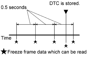
The ECM records engine conditions in the form of freeze frame data every 0.5 seconds. Using the intelligent tester, 5 separate sets of freeze frame data can be checked.
These data sets can be used to simulate the condition of the vehicle from around the time of the occurrence of the malfunction. The data may assist in identifying the cause of the malfunction, and in judging whether it was temporary or not.
 |
- HINT:
- If it is impossible to duplicate the problem even though a DTC is output, confirm the freeze frame data.
- 3 data sets from before the DTC was stored
- 1 data set from when the DTC was stored
- 1 data set from after the DTC was stored
| LIST OF FREEZE FRAME DATA |
| Label (Tester Display) | Measurement Item/Range | Diagnostic Note |
| Vehicle Speed | Vehicle speed | Speed indicated on the speedometer. |
| Engine Speed | Engine speed | - |
| Calculate Load | Calculated load | Load calculated by the ECM. |
| Vehicle Load | Vehicle load | - |
| MAF | Mass air flow volume | If the value is approximately 0.0 gm/s:
|
| Atmosphere Pressure | Atmospheric pressure | - |
| Coolant Temp | Engine coolant temperature | If the value is -40°C, the sensor circuit is open. If the value is 140°C, the sensor circuit is shorted. |
| Intake Air | Intake air temperature | If the value is -40°C, the sensor circuit is open. If the value is 140°C, the sensor circuit is shorted. |
| Engine Run Time | Accumulated engine running time | - |
| Initial Engine Coolant Temp | Initial engine coolant temperature | - |
| Initial Intake Air Temp | Initial intake air temperature | - |
| Battery Voltage | Battery voltage | - |
| Accel Sens. No. 1 Volt % | Absolute No. 1 accelerator pedal position | - |
| Accel Sens. No. 2 Volt % | Absolute No. 2 accelerator pedal position | - |
| Throttle Sensor Volt % | Throttle sensor position | Read the value with the ignition switch ON (do not start engine). |
| Throttle Sensor #2 Volt % | Throttle sensor position #2 | - |
| Throttle Sensor Position | Throttle position | Read the value with the ignition switch ON (do not start engine). |
| Throttle Motor DUTY | Throttle actuator | - |
| Throttle Position | Throttle position | For use when engine stall, starting problems or rough idle is present. |
| ISC Flow | Flow rate calculated using information from each sensor | For use when engine stall, starting problems or rough idle is present. |
| ISC Position | Requested opening amount calculated using ISC control | For use when engine stall, starting problems or rough idle is present. |
| ISC Feedback Value | ISC feedback compensation amount | For use when engine stall, starting problems or rough idle is present. |
| ISC Learning Value | ISC learned compensation amount | For use when engine stall, starting problems or rough idle is present. |
| Electric Load Feedback Val | Compensation flow rate according to electrical load | For use when engine stall, starting problems or rough idle is present. |
| Air Conditioner FB Val | Compensation flow rate according to air conditioner load | For use when engine stall, starting problems or rough idle is present. |
| PS Feedback Val | Compensation flow rate according to power steering load | For use when engine stall, starting problems or rough idle is present. |
| Low Revolution Control | Low engine speed control operation state | For use when engine stall, starting problems or rough idle is present. |
| Neutral Control | Neutral control operation state | For use when engine stall, starting problems or rough idle is present. |
| N Range Status | Shift lever N status | For use when engine stall, starting problems or rough idle is present. |
| Eng Stall Control FB Flow | Intake air compensation flow rate | For use when engine stall, starting problems or rough idle is present. |
| Deposit Loss Flow | Deposit loss flow rate | For use when engine stall, starting problems or rough idle is present. |
| Injector (Port) | Injection period of No. 1 cylinder | - |
| Injection Volum (Cylinder 1) | Injection volume | - |
| Fuel Pump/Speed Status | Fuel pump status | - |
| EVAP (Purge) VSV | EVAP purge VSV duty ratio | - |
| Evap Purge Flow | Ratio of evaporative purge flow to intake air volume | - |
| Purge Density Learn Value | Purge density learned value | - |
| EVAP Purge VSV | EVAP purge VSV | - |
| Purge Cut VSV Duty | Purge cut VSV duty | - |
| Target Air-Fuel Ratio | Air-fuel ratio | - |
| AF Lambda B1S1 | Fuel trim at air fuel ratio sensor | - |
| AFS Voltage B1S1 | Air fuel ratio sensor output | Performing the Control the Injection Volume or Control the Injection Volume for A/F Sensor function of the Active Test enables the technician to check the output voltage of the air fuel ratio sensor. |
| AFS Current B1S1 | Air fuel ratio sensor current | - |
| A/F Heater Duty #1 | Air fuel ratio sensor heater duty ratio | - |
| O2S B1S2 | Heated oxygen sensor output | Performing the Control the Injection Volume or Control the Injection Volume for A/F Sensor function of the Active Test enables the technician to check the output voltage of the heated oxygen sensor. |
| O2S Impedance B1 S2 | Heated oxygen sensor impedance for bank 1 sensor 2 | - |
| O2 Heater B1S2 | Heated oxygen sensor heater | - |
| O2 Heater Curr Val B1S2 | Heated oxygen sensor current | - |
| Short FT #1 | Short-term fuel trim | Short-term fuel compensation is used to maintain the air-fuel ratio at the stoichiometric air-fuel ratio. |
| Long FT #1 | Long-term fuel trim | Overall fuel compensation is carried out in the long term to compensate for a continual deviation of the short-term fuel trim from the central value. |
| Total FT #1 | Total fuel trim | - |
| Fuel System Status #1 | Fuel system status (Bank 1) |
|
| Fuel System Status #2 | Fuel system status (Bank 2) | - |
| IGN Advance | Ignition timing advance for No. 1 cylinder | - |
| Knock Feedback Value | Knocking feedback value | - |
| Knock Correct Learn Value | Knocking correction learned value | - |
| Idle Spark Advn Ctrl #1 | Individual cylinder timing advance compensation amount (No. 1) | For use when engine stall, starting problems or rough idle is present. |
| Idle Spark Advn Ctrl #2 | Individual cylinder timing advance compensation amount (No. 2) | For use when engine stall, starting problems or rough idle is present. |
| Idle Spark Advn Ctrl #3 | Individual cylinder timing advance compensation amount (No. 3) | For use when engine stall, starting problems or rough idle is present. |
| Idle Spark Advn Ctrl #4 | Individual cylinder timing advance compensation amount (No. 4) | For use when engine stall, starting problems or rough idle is present. |
| Actual VVT Angle #1 | VVT angle status | - |
| VVT Control Status #1 | VVT control status | - |
| VVT Advance Fail | VVT control failure status | - |
| Catalyst Temp B1S1 | Catalyst temperature | - |
| Catalyst Temp B1S2 | Catalyst temperature | - |
| Starter Signal | Starter signal | - |
| Starter Control | Starter control signal | - |
| Power Steering Signal | Power steering signal | - |
| Starter Relay | Starter Relay status | - |
| ACC Relay | ACC Relay status | - |
| Neutral Position SW Signal | Park/neutral position switch signal | - |
| Stop Light Switch | Stop light switch | - |
| A/C Signal | A/C signal | - |
| Closed Throttle Position SW | Closed throttle position switch | - |
| Fuel Cut Condition | Fuel cut condition | - |
| TC Terminal | TC terminal status | - |
| Time after DTC Cleared | Cumulative time after DTCs cleared | - |
| Distance from DTC Cleared | Accumulated distance driven after DTCs cleared | - |
| Warmup Cycle Cleared DTC | Warmup cycles after DTCs cleared | - |
| Dist Batt Cable Disconnect | Total distance vehicle driven after battery cable disconnected | - |
| TC and TE1 | TC and CG (TE1) terminals of DLC3 | - |
| Ignition Trig. Count | Ignition counter | - |
| Cylinder #1 Misfire Count | Cylinder #1 misfire count | - |
| Cylinder #2 Misfire Count | Cylinder #2 misfire count | - |
| Cylinder #3 Misfire Count | Cylinder #3 misfire count | - |
| Cylinder #4 Misfire Count | Cylinder #4 misfire count | - |
| All Cylinders Misfire Rate | Misfire count of all cylinders | - |
| Misfire RPM | Misfire RPM | - |
| Misfire Load | Misfire load | - |
| Misfire Margin | Misfire monitoring | - |
| Catalyst OT MF F/C | Availability of fuel-cut function to prevent misfire causing catalyst overheat | - |
| Cat OT MF F/C History | History of fuel-cut function to prevent misfire causing catalyst overheat | - |
| Cat OT MF F/C Cylinder#1 | Display of fuel cut operation in No. 1 cylinder (if certain level of misfire malfunction is detected) | - |
| Cat OT MF F/C Cylinder#2 | Display of fuel cut operation in No. 2 cylinder (if certain level of misfire malfunction is detected) | - |
| Cat OT MF F/C Cylinder#3 | Display of fuel cut operation in No. 3 cylinder (if certain level of misfire malfunction is detected) | - |
| Cat OT MF F/C Cylinder#4 | Display of fuel cut operation in No. 4 cylinder (if certain level of misfire malfunction is detected) | - |
| Engine Speed (Starter Off) | Engine speed when starter off | For use when engine stall, starting problems or rough idle is present. |
| Starter Count | Number of times starter turned on after ignition switch turned to ON | For use when engine stall, starting problems or rough idle is present. |
| Run Dist of Previous Trip | Distance driven during previous trip | For use when engine stall, starting problems or rough idle is present. |
| Engine Starting Time | Time elapsed after engine started (interval between ignition switch ON and off) | For use when engine stall, starting problems or rough idle is present. |
| Previous Trip Coolant Temp | Engine coolant temperature during previous trip | For use when engine stall, starting problems or rough idle is present. |
| Previous Trip Intake Temp | Intake air temperature during previous trip | For use when engine stall, starting problems or rough idle is present. |
| Engine Oil Temperature | Engine oil temperature (estimated temperature) | For use when engine stall, starting problems or rough idle is present. |
| Previous Trip Eng Oil Temp | Engine oil temperature during previous trip | For use when engine stall, starting problems or rough idle is present. |
| Ambient Temp for A/C | Ambient temperature for A/C | For use when engine stall, starting problems or rough idle is present. |
| Previous Trip Ambient Temp | Ambient temperature during previous trip | For use when engine stall, starting problems or rough idle is present. |
| Engine Start Hesitation | History of hesitation during engine start | For use when engine stall, starting problems or rough idle is present. |
| Low Rev for Eng Start | History of low engine speed after engine start | For use when engine stall, starting problems or rough idle is present. |
| Minimum Engine Speed | Minimum engine speed | For use when engine stall, starting problems or rough idle is present. |
| Battery Current | Battery current | Charging control service data |
| Battery Temperature | Battery temperature | Charging control service data |
| Alternator Output Duty | Alternator output duty | Electricity generated by alternator is output through duty ratio Charging control service data |
| Alt Vol - Non Active Test | Request voltage when regulator not under forced activation | Alternator regulator output voltage is output |
| Alt Vol - Active Test | Request voltage when regulator under forced activation | Charging control service data |
| Electric Fan Motor | Electric fan motor | - |
| Idle Fuel Cut | Fuel cut at idle | ON: The throttle valve is fully closed and the engine speed is more than 3500 rpm. |
| FC TAU | Fuel cut during very light load | Fuel cut is being performed under a very light load to prevent the engine combustion from becoming incomplete. |
| Immobiliser Fuel Cut | Status of the immobiliser fuel cut | - |
| Electrical Load Signal 1 | Electrical load signal | - |
| Electrical Load Signal 3 | Electrical load signal | - |