Lexus IS250 IS220d GSE20 ALE20 2AD-FHV ENGINE MECHANICAL
ENGINE UNIT - DISASSEMBLY
| 1. REMOVE CAM POSITION SENSOR |
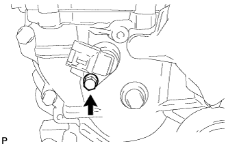
Remove the bolt and cam position sensor.
| 2. REMOVE CRANK POSITION SENSOR |
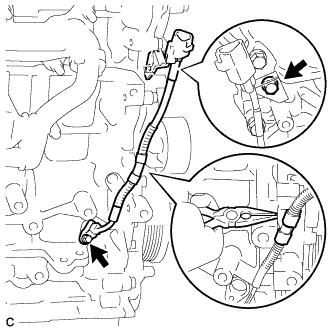
Remove the 2 bolts, clamp and crank position sensor.
| 3. REMOVE CYLINDER HEAD COVER SUB-ASSEMBLY |
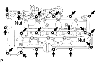
Disconnect the ventilation hose.
Remove the 13 bolts, 2 nuts, 2 washers, 4 nozzle holder clamp seats and cylinder head cover sub-assembly.
Remove the cylinder head cover gasket and No. 2 cylinder head cover gasket.
Remove the 2 engine cover joints.
| 4. REMOVE OIL FILLER CAP SUB-ASSEMBLY |
Remove the oil filler cap and gasket.
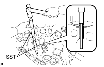
| 5. REMOVE NO. 2 OIL PAN SUB-ASSEMBLY |
Remove the drain plug and gasket.
Remove the 16 bolts and 2 nuts.

Insert the blade of the SST between the oil pan and No. 2 oil pan, and cut through the applied sealer and remove the oil pan.
- SST
- 09032-00100
- NOTICE:
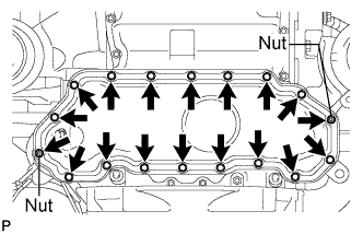
| 6. REMOVE OIL PAN SUB-ASSEMBLY |
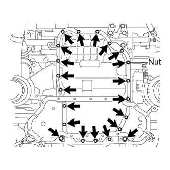
Remove the 20 bolts and nut.
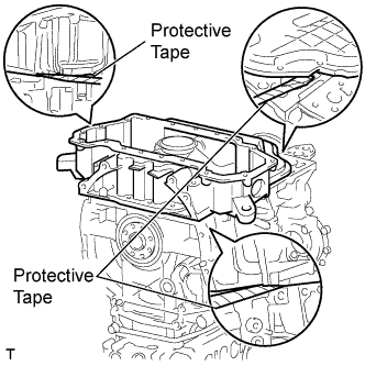
Remove the oil pan by prying between the oil pan and cylinder block with a screwdriver.
- NOTICE:
- Be careful not to damage the contact surfaces of the cylinder block and oil pan.
- HINT:
- Tape the screwdriver tip before use.
| 7. REMOVE OIL FILTER ELEMENT |
- HINT:
| 8. REMOVE OIL FILTER BRACKET |
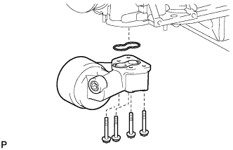
Remove the 4 bolts, oil filter bracket and gasket.
| 9. REMOVE OIL STRAINER SUB-ASSEMBLY |
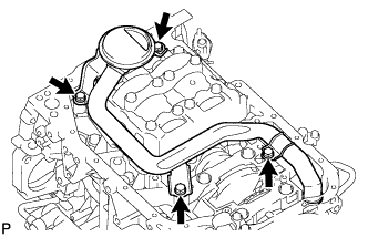
Remove the 4 bolts, oil strainer and O-ring.
| 10. REMOVE CRANKSHAFT PULLEY |
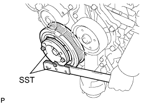
Using SST, remove the bolt holding the crankshaft.
- SST
- 09213-58013
09330-00021
Insert the service bolt.
- Recommended service bolt:
Item Specified Condition Thread diameter 12 mm (0.47 in.) Thread pitch 1.5 mm (0.059 in.) Bolt length Approx. 30 to 38 mm (1.18 to 1.50 in.)
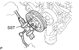
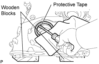
Using SST, remove the crankshaft pulley.
- SST
- 09950-50013(09951-05010,09952-05010,09953-05020,09954-05021)
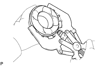
| 11. REMOVE WATER PUMP ASSEMBLY |
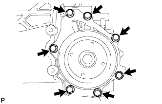
Remove the 7 bolts and water pump assembly.
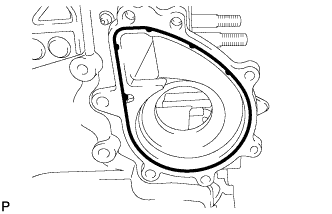
Remove the gasket.
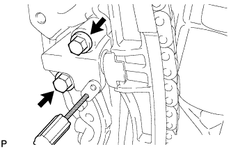
| 12. REMOVE TIMING CHAIN COVER SUB-ASSEMBLY |
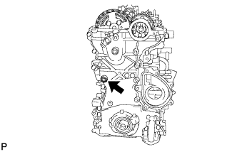
Using a 10 mm socket hexagon wrench, remove the timing chain cover plug and gasket.
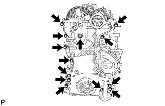
Remove the 13 bolts and seal washer shown in the illustration.
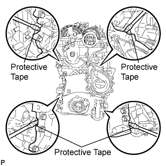
Remove the timing chain cover by prying between the timing chain cover and cylinder head or cylinder block with a screwdriver.
- HINT:
- Tape the screwdriver tip before use.
- NOTICE:
- Do not damage the contact surfaces of the cylinder head, cylinder block and timing chain cover.
Remove the gasket and O-ring.
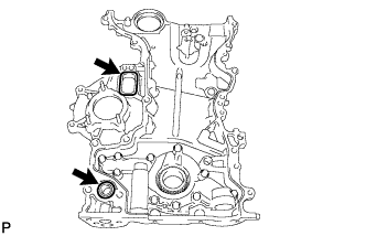
| 13. REMOVE TIMING CHAIN CASE OIL SEAL |
Using a screwdriver, pry out the oil seal.
- HINT:
- Tape the screwdriver tip before use.
- NOTICE:
- Do not damage the surface of the oil seal press fit hole.
| 14. REMOVE ENGINE BALANCER ASSEMBLY |
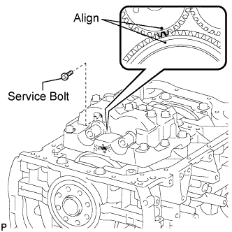
Align the timing marks of the drive and driven gears (1 dot mark each) by turning the crankshaft with a wrench.
Install the service bolt.
- Recommended service bolt:
Item Specified Condition Thread diameter 6 mm (0.24 in.) Thread pitch 1 mm (0.04 in.) Bolt length 16 to 18 mm (0.63 to 0.71 in.)
- Torque:
- 1.5 N*m{ 15.3 kgf*cm, 13.3 in.*lbf}
- HINT:
- When removing the balancer assembly, make certain that the torsional spring force of the sub gear has been eliminated by installing the service bolt.
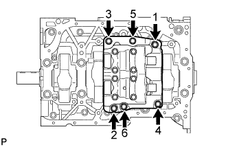
Uniformly loosen the 6 bolts in several steps, in the sequence shown in the illustration.
Remove the engine balancer assembly.
| 15. REMOVE NO. 1 CHAIN TENSIONER ASSEMBLY |
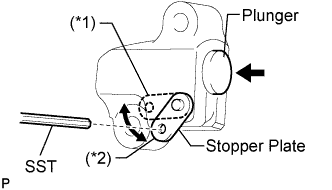
Move the stopper plate upward to release the lock, and push the plunger deep into the tensioner (*1).
Move the stopper plate downward to set the lock, and insert SST into the stopper plate hole (*2).
- SST
- 09240-00020(09242-00200)
Remove the 2 bolts and chain tensioner assembly.
| 16. REMOVE CHAIN TENSIONER SLIPPER |
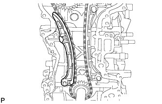
Remove the tensioner slipper.
| 17. REMOVE NO. 1 CHAIN VIBRATION DAMPER |
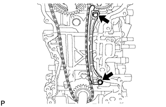
Remove the 2 bolts and vibration damper.
| 18. REMOVE CAMSHAFT TIMING SPROCKET |
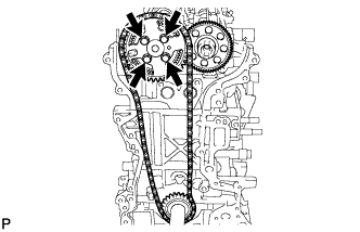
Remove the 4 bolts, camshaft timing sprocket, crankshaft timing sprocket and chain.
| 19. REMOVE CAMSHAFT |
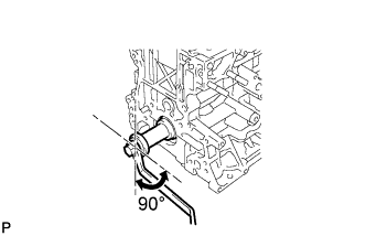
Using the crankshaft pulley bolt, set the No. 1 cylinder to 90° BTDC/compression.
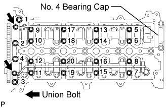
Remove the 2 union bolts.
Using several steps, loosen and remove the 20 bearing cap bolts uniformly in the sequence shown in the illustration.
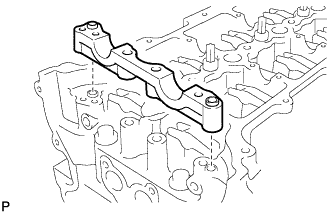
Remove the 8 No. 3 bearing caps, No. 1 bearing cap and 2 oil delivery pipes.
- HINT:
- Do not remove the No. 4 bearing cap.
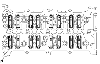
Remove the camshaft.
| 20. REMOVE NO. 2 CAMSHAFT |
Remove the No. 2 camshaft.
Remove the No. 2 bearing cap.
| 21. REMOVE NO. 1 VALVE ROCKER ARM SUB-ASSEMBLY |
Remove the 16 No. 1 valve rocker arm sub-assemblies.
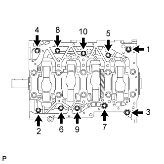
| 22. REMOVE CYLINDER HEAD SUB-ASSEMBLY |
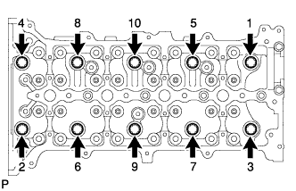
Uniformly loosen the 10 bolts in the sequence shown in the illustration. Remove the 10 cylinder head bolts and plate washers.
- NOTICE:
Remove the cylinder head.
| 23. REMOVE CYLINDER HEAD GASKET |
Remove the cylinder head gasket.
| 24. REMOVE VALVE LASH ADJUSTER ASSEMBLY |
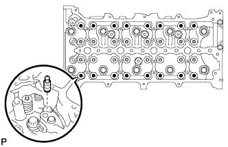
Remove the valve lash adjusters from the cylinder head.
- HINT:
- Arrange the removed parts in the correct order.
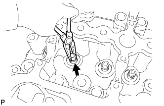
| 25. REMOVE INTAKE VALVE |
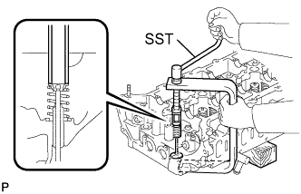
Using SST and wooden blocks, compress the compression spring and remove the valve retainer locks.
- SST
- 09202-70020
Remove the retainer, compression spring, and valve.
- HINT:
- Arrange the removed parts in the correct order.
| 26. REMOVE EXHAUST VALVE |
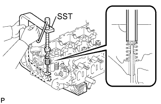
Using SST and wooden blocks, compress the compression spring and remove the valve retainer locks.
- SST
- 09202-70020
Remove the retainer, compression spring, and valve.
- HINT:
- Arrange the removed parts in the correct order.
| 27. REMOVE VALVE STEM OIL SEAL |
Using needle-nose pliers, remove the oil seals.
| 28. REMOVE VALVE SPRING SEAT PLATE WASHER |
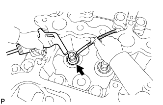
Using compressed air and a magnetic finger, remove the valve spring seat by blowing air onto it.
| 29. REMOVE INTAKE VALVE GUIDE BUSH |
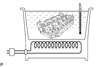
Gradually heat the cylinder head to approximately 80 to 100°C (176 to 212°F).
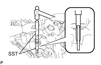
Using SST and a hammer, tap out the valve guide bush.
- SST
- 09201-10000
09950-70010
| 30. REMOVE EXHAUST VALVE GUIDE BUSH |
Gradually heat the cylinder head to approximately 80 to 100°C (176 to 212°F).
Using SST and a hammer, tap out the valve guide bush.
- SST
- 09201-10000
09950-70010
| 31. REMOVE PISTON SUB-ASSEMBLY WITH CONNECTING ROD |
- NOTICE:
- The matchmarks on the connecting rods and caps are for ensuring the correct reassembly.
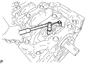
Remove the 2 connecting rod cap bolts.
Using the 2 removed connecting rod cap bolts, remove the connecting rod cap and lower bearing by wiggling the connecting rod cap right and left.
- HINT:
- Keep the lower bearing inserted to the connecting rod cap.
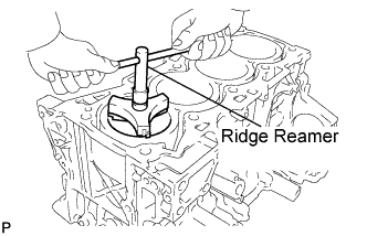
Using a ridge reamer, remove all the carbon from the top of the cylinder.
Push the piston, connecting rod assembly and upper bearing through the top of the cylinder block.
- HINT:
| 32. REMOVE CONNECTING ROD BEARING |
- HINT:
- Arrange the removed parts in the correct order.
| 33. REMOVE CRANKSHAFT |
Uniformly loosen the 10 bolts in several steps, in the sequence shown in the illustration.
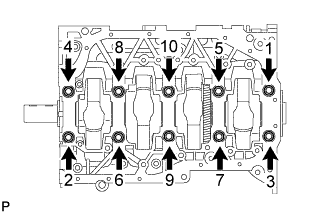
Uniformly loosen the 10 bearing cap bolts in several steps, in the sequence shown in the illustration.
- HINT:

Remove the crankshaft bearing cap sub-assembly by prying between the crankshaft bearing cap sub-assembly and cylinder block with a screwdriver.
- HINT:
- Tape the screwdriver tip before use.
- NOTICE:
- Do not damage the contact surfaces of the cylinder block and crankshaft bearing cap sub-assembly.
Lift out the crankshaft.
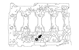
Using a 6 mm hexagon wrench, remove the screw plug.
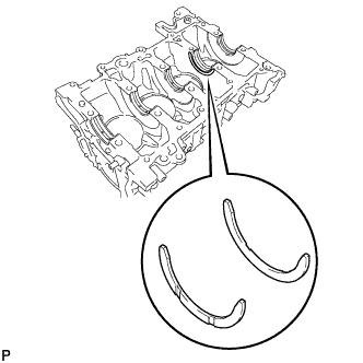
Remove the upper bearings and upper thrust washers from the cylinder block.
- HINT:
- Arrange the bearings and thrust washers in the correct order.
| 34. REMOVE NO. 2 CRANKSHAFT BEARING |
Remove the lower bearings from the crankshaft bearing cap sub-assembly.
- HINT:
- Arrange the bearings in the correct order.
| 35. REMOVE ENGINE REAR OIL SEAL |
Remove the rear oil seal from the crankshaft.
| 36. REMOVE NO. 1 CRANKSHAFT POSITION SENSOR PLATE |
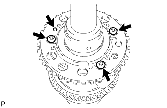
Using a "torx" socket wrench (T30), remove the 3 bolts and the crankshaft position sensor plate.
| 37. REMOVE PISTON RING SET |
- HINT:
- Arrange the piston rings in the correct order.
Using a piston ring expander, remove the 2 compression rings.
Using a piston ring expander, remove the oil ring rail.
Remove the oil ring expander by hand.
| 38. REMOVE CYLINDER BLOCK WATER DRAIN COCK SUB-ASSEMBLY |
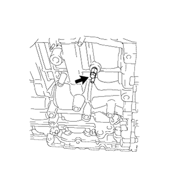
Remove the water drain cock sub-assembly from the cylinder block.
Remove the water drain cock plug from the water drain cock sub-assembly.
| 39. REMOVE PISTON WITH PIN SUB-ASSEMBLY |
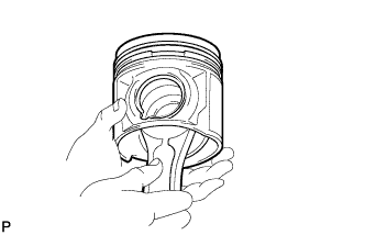
Check the fitting condition between the piston and piston pin.
Try to move the piston back and forth on the piston pin.
- HINT:
- If any movement is felt, replace the piston and pin as a set.
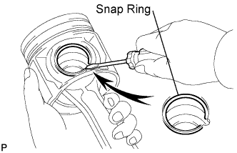
Disconnect the connecting rod from the piston.
Using a screwdriver, pry off the snap rings from the piston.
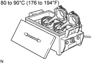
Gradually heat the piston to approximately 80 to 90°C (176 to 194°F).
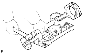
Using a brass bar and plastic hammer, lightly tap out the piston pin and remove the connecting rod.
- HINT:
| 40. CLEAN PISTON SUB-ASSEMBLY |
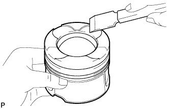
Using a gasket scraper, remove the carbon from the piston top.
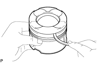
Using a groove cleaning tool or broken ring, clean the piston ring grooves.
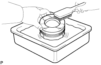
Using solvent and a brush, thoroughly clean the piston.
- NOTICE:
- Do not use a wire brush.
| 41. REMOVE NO. 1 OIL NOZZLE SUB-ASSEMBLY |
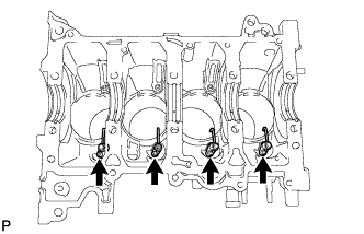
Using a 5 mm hexagon wrench, remove the oil nozzles.
| 42. REMOVE OIL REFLECTOR PLATE |
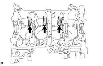
Using a 5 mm hexagon wrench, remove the reflector plates.
| 43. CLEAN CYLINDER BLOCK |
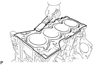
Using a gasket scraper, remove all the gasket material from the top surface of the cylinder block.
Using a soft brush and solvent, thoroughly clean the cylinder block.