Lexus IS250 IS220d GSE20 ALE20 2AD-FHV ENGINE CONTROL SYSTEM
READ VALUE OF INTELLIGENT TESTER (ACCELERATOR PEDAL POSITION SENSOR VALUE)
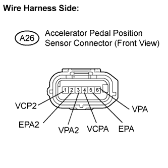
CHECK HARNESS AND CONNECTOR (ACCELERATOR PEDAL POSITION SENSOR - ECM)
INSPECT ECM TERMINAL VOLTAGE (VCPA AND VCP2 TERMINALS)
REPLACE ACCELERATOR PEDAL ROD ASSEMBLY
DTC P2120 Throttle / Pedal Position Sensor / Switch "D" Circuit
DTC P2122 Throttle / Pedal Position Sensor / Switch "D" Circuit Low Input
DTC P2123 Throttle / Pedal Position Sensor / Switch "D" Circuit High Input
DTC P2125 Throttle / Pedal Position Sensor / Switch "E" Circuit
DTC P2127 Throttle / Pedal Position Sensor / Switch "E" Circuit Low Input
DTC P2128 Throttle / Pedal Position Sensor / Switch "E" Circuit High Input
DTC P2138 Throttle / Pedal Position Sensor / Switch "D" / "E" Voltage Correlation
DESCRIPTION
- HINT:
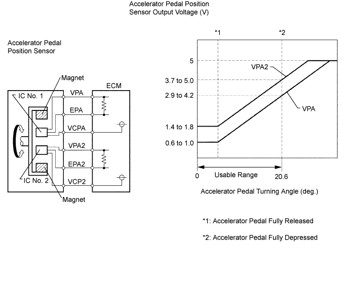
The accelerator pedal position sensor is mounted on the accelerator pedal and detects the opening angle of the accelerator pedal. Since this sensor is electronically controlled with Hall-effect elements, accurate control and reliability can be obtained. It has 2 sensors to detect the accelerator position and a malfunction of the accelerator position sensor.
In the accelerator pedal position sensor, the voltage applied to pedal terminals VPA and VPA2 of the ECM changes between 0 V and 5 V in proportion to the opening angle of the accelerator pedal. The VPA is a signal to indicate the actual accelerator pedal opening angle which is used for the engine control, and the VPA2 is a signal to indicate the information about the opening angle which is used for detecting malfunctions. The ECM judges the current opening angle of the accelerator pedal using signals from terminals VPA and VPA2, and the ECM controls the throttle motor based on these signals.
| DTC No. | DTC Detection Condition (All of following are 1 trip detection logic) | Trouble Area |
| P2120 | Condition (a) or (b) continues for 0.5 sec. or more: (a) VPA is 0.4 V or less (b) VPA is 4.8 V or more |
Accelerator pedal position sensor Accelerator pedal Accelerator pedal rod (arm) deformed ECM |
| P2122 | VPA is 0.4 V or less for 0.5 sec. or more when VPA2 output indicates that accelerator pedal is depressed | Accelerator pedal position sensor Open in VCPA circuit VPA circuit open or ground short Accelerator pedal Accelerator pedal rod (arm) deformed ECM |
| P2123 | Condition (a) continues for 2.0 sec. or more: (a) VPA is 4.8 V or more |
Accelerator pedal position sensor Open in EPA circuit Accelerator pedal Accelerator pedal rod (arm) deformed ECM |
| P2125 | Condition (a) or (b) continues for 0.5 sec. or more: (a) VPA2 is 1.2 V or less (b) VPA2 is 4.8 V or more |
Accelerator pedal position sensor Accelerator pedal Accelerator pedal rod (arm) deformed ECM |
| P2127 | VPA2 is 1.2 V or less for 0.5 sec. or more when VPA output indicates accelerator pedal is opened | Accelerator pedal position sensor Open in VCP2 circuit VPA2 circuit open or ground short Accelerator pedal Accelerator pedal rod (arm) deformed ECM |
| P2128 | Conditions (a) and (b) continue for 2.0 sec. or more: (a) VPA2 is 4.8 V or more (b) VPA is 0.4 V or more and VPA is 3.45 V or less |
Accelerator pedal position sensor Open in EPA2 circuit Accelerator pedal Accelerator pedal rod (arm) deformed ECM |
| P2138 | Condition (a) or (b) continues for 2.0 sec. or more: (a) Difference between VPA and VPA2 is 0.02 V or less (b) VPA is 0.4 V or less and VPA2 is 1.2 V or less |
VPA and VPA2 circuits are short circuited Accelerator pedal position sensor Accelerator pedal Accelerator pedal rod (arm) deformed ECM |
- HINT:
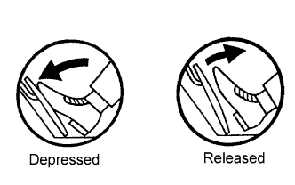
- When DTC P2120, P2122, P2123, P2125, P2127, P2128, or P2138 is detected, check the output voltage of the accelerator pedal position sensor by entering the following menus on the intelligent tester: Powertrain / Engine / Data List / Accel Position 1 and Accel Position 2.
| - | Accelerator pedal position expressed as voltage output | Accelerator pedal position expressed as voltage output | Accelerator pedal position expressed as voltage output | Accelerator pedal position expressed as voltage output |
| - | Accelerator pedal released | Accelerator pedal released | Accelerator pedal depressed | Accelerator pedal depressed |
| Trouble Area | Accelerator Position No. 1 | Accelerator Position No. 2 | Accelerator Position No. 1 | Accelerator Position No. 2 |
| VCP circuit open | 0 to 0.2 V | 0 to 0.2 V | 0 to 0.2 V | 0 to 0.2 V |
| VPA circuit open or ground short | 0 to 0.2 V | 0.9 to 2.3 V | 0 to 0.2 V | 3.4 to 5.0 V |
| VPA2 circuit open or ground short | 0.5 to 1.1 V | 0 to 0.2 V | 3.0 to 4.6 V | 0 to 0.2 V |
| EP circuit open | 4.5 to 5.0 V | 4.5 to 5.0 V | 4.5 to 5.0 V | 4.5 to 5.0 V |
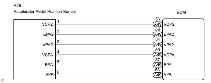
WIRING DIAGRAM
INSPECTION PROCEDURE
- NOTICE:
- After replacing the ECM, the new ECM needs registration and initialization .
| 1.READ VALUE OF INTELLIGENT TESTER (ACCELERATOR PEDAL POSITION SENSOR VALUE) |
Connect the intelligent tester to the DLC3.
Turn the engine switch ON (IG) and turn the intelligent tester ON.
Enter the following menus: Powertrain / Engine / Data List / Accel Position 1 and Accel Position 2.
Read the values.
- Standard voltage:
Accelerator Pedal Accel Position 1 Accel Position 2 Released 0.5 to 1.1 V 0.9 to 2.3 V Depressed 3.0 to 4.6 V 3.4 to 5.0 V
|
| ||||
| NG | |
| 2.CHECK HARNESS AND CONNECTOR (ACCELERATOR PEDAL POSITION SENSOR - ECM) |
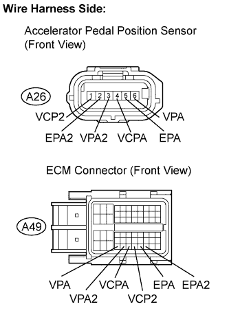
Disconnect the A26 sensor connector.
Disconnect the A49 ECM connector.
Measure the resistance of the wire harness side connectors.
- Standard resistance:
Tester Connection Specified Condition VCP2 (A26-1) - VCP2 (A49-56) Below 1 Ω EPA2 (A26-2) - EPA2 (A49-58) Below 1 Ω VPA2 (A26-3) - VPA2 (A49-54) Below 1 Ω VCPA (A26-4) - VCPA (A49-55) Below 1 Ω EPA (A26-5) - EPA (A49-57) Below 1 Ω VPA (A26-6) - VPA (A49-53) Below 1 Ω VCP2 (A26-1) or VCP2 (A49-56) - Body ground 10 kΩ or higher EPA2 (A26-2) or EPA2 (A49-58) - Body ground 10 kΩ or higher VPA2 (A26-3) or VPA2 (A49-54) - Body ground 10 kΩ or higher VCPA (A26-4) or VCPA (A49-55) - Body ground 10 kΩ or higher EPA (A26-5) or EPA (A49-57) - Body ground 10 kΩ or higher VPA (A26-6) or VPA (A49-53) - Body ground 10 kΩ or higher
|
| ||||
| OK | |
| 3.INSPECT ECM TERMINAL VOLTAGE (VCPA AND VCP2 TERMINALS) |
Disconnect the A26 sensor connector.
Turn the engine switch ON (IG).
Measure the voltage of the sensor connector.
- Standard voltage:
Tester Connection Specified Condition VCPA (A26-4) - EPA (A26-5) 4.5 to 5.5 V VCP2 (A26-1) - EPA2 (A26-2)
|
| ||||
| OK | |
| 4.REPLACE ACCELERATOR PEDAL ROD ASSEMBLY |
| NEXT | |
| 5.CHECK IF OUTPUT DTC RECURS |
Clear the DTC .
Start the engine.
Drive the engine at idle for 15 seconds or more.
Read the DTC .
- Result:
Display (DTC output) Proceed to P2120, P2122, P2123, P2125, P2127, P2128, or P2138 is output again A P2120, P2122, P2123, P2125, P2127, P2128, or P2138 is not output B
|
| ||||
| A | ||
| ||