Lexus IS250 IS220d GSE20 ALE20 2AD-FHV ENGINE CONTROL SYSTEM
INSPECT EXHAUST FUEL ADDITION INJECTOR (RESISTANCE)
CHECK HARNESS AND CONNECTOR (EXHAUST FUEL ADDITION INJECTOR - ECM)
DTC P2047 Reductant Injector Circuit / Open (Bank 1 Unit 1)
DTC P2048 Short to GND in Reductant Injector Circuit (Bank 1)
DTC P2049 Short to B+ in Reductant Injector Circuit (Bank 1)
DESCRIPTION
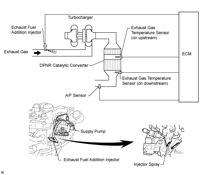
The exhaust fuel addition injector is mounted on the exhaust port of the cylinder head, and low pressure is provided to the injector by the feed pump in the supply pump. This injector adds fuel by a control signal from the ECM.
This injector is used for two different controls: DPNR catalyst regeneration and nitrogen oxides (NOx) reduction.
Under the DPNR catalyst regeneration control, the injector adds fuel to raise a catalyst temperature.
In the other control, the injector helps the air-fuel ratio become RICH. As a result, NOx in the exhaust gas will be reduced in response to the RICH air-fuel ratio.
- HINT:
- *1: Diesel Clean Advanced Technology.
| DTC No. | DTC Detection Condition | Trouble Area |
| P2047 | With the exhaust fuel addition injector off, the FIVM1 output is High and the FIVM2 output is Low for 3 seconds. (1 trip detection logic) | Open in exhaust fuel addition injector circuit Exhaust fuel addition injector ECM |
| P2048 | With the exhaust fuel addition injector off, the FIVM1 output is High and the FIVM2 output is High for 0.16 seconds. (1 trip detection logic) | |
| P2049 | With the exhaust fuel addition injector on, the FIVM1 output is Low and the FIVM2 output is Low 7 or more times. (1 trip detection logic) |
- HINT:
- DTC P1386 (injector for exhaust fuel addition) will be present if there is an open malfunction in the exhaust fuel addition injector circuit.
MONITOR DESCRIPTION
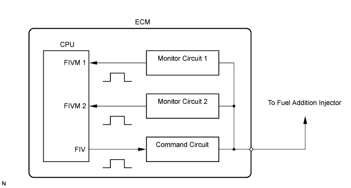
In order to detect abnormality in the fuel addition injector, an internal CPU of the ECM monitors injection command (FIV) signals and injection confirmation (FIVM) signals. The FIV signal is sent from the CPU to the (exhaust) fuel addition injector via a drive circuit inside the ECM. The FIVM signal, which is originally output current from the internal drive circuit of the ECM, is transmitted to the CPU via a monitor circuit. By receiving the FIVM signal, the ECM judges that the current has been applied to the (exhaust) fuel addition injector.
This DTC will be set if the ECM judges that the number of signals of the FIV and the FIVM are inconsistent.
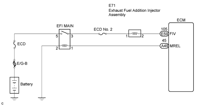
WIRING DIAGRAM
INSPECTION PROCEDURE
- NOTICE:
- After replacing the ECM, the new ECM needs registration and initialization .
| 1.INSPECT EXHAUST FUEL ADDITION INJECTOR (RESISTANCE) |
Inspect exhaust fuel addition injector injection .
|
| ||||
| OK | |
| 2.CHECK HARNESS AND CONNECTOR (EXHAUST FUEL ADDITION INJECTOR - ECM) |
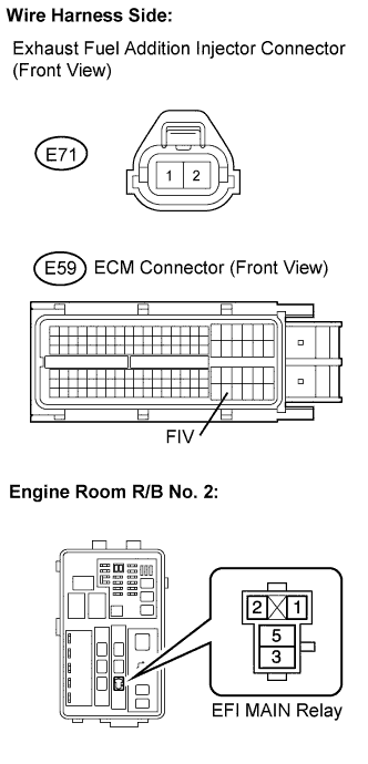
Disconnect the E71 exhaust fuel addition injector assembly connector.
Disconnect the E59 ECM connector.
Remove the EFI MAIN relay from the engine room R/B No. 2.
Check the resistance between the wire harness side connectors.
- Standard resistance (Check for open):
Tester Connection Specified Condition FIV (E59-105) - Injector Connector (E71-1) Below 1 Ω EFI MAIN Relay (3) - Injector Connector (E71-2) Below 1 Ω
- Standard resistance (Check for short):
Tester Connection Specified Condition FIV (E59-105) or FIV (E71-1) - Body ground 10 kΩ or higher
Reconnect the exhaust fuel addition injector assembly connector.
Reconnect the ECM connector.
Reinstall the EFI MAIN relay.
|
| ||||
| OK | ||
| ||