Back Door -- Reassembly |
- HINT:
- A bolt without a torque specification is shown in the standard bolt chart (Toyota Fortuner RM00000118W017X.html).
| 1. INSTALL BACK DOOR STAY ASSEMBLY LH |
When using a new bolt:
Clean the threaded portion on the vehicle body with a non-residue solvent.
When reusing a bolt:
Clean the threaded portion on the vehicle body and bolt with a non-residue solvent.
Apply adhesive to the threads of the bolt.
- Adhesive:
- Toyota Genuine Adhesive 1324, Three Bond 1324 or equivalent
Install the back door stay with the 4 bolts.
- Torque:
- 7.5 N*m{76 kgf*cm, 66 in.*lbf}
- CAUTION:
- Install the back door stay while holding the back door.
| 2. INSTALL BACK DOOR STAY ASSEMBLY RH |
- HINT:
- Use the same procedure described for the LH side.
| 3. INSTALL BACK DOOR LOWER STOPPER |
- HINT:
- Use the same procedure for both back door lower stoppers.
Install the back door lower stopper with the bolt.
- Torque:
- 7.0 N*m{71 kgf*cm, 62 in.*lbf}
| 4. INSTALL BACK DOOR PANEL CUSHION |
- HINT:
- Use the same procedure for both back door panel cushions.
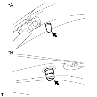
Install 2 new back door panel cushions.
Text in Illustration *1 for Upper Side *2 for Lower Side
 |
| 5. INSTALL BACK DOOR GLASS CHANNEL LH |
- HINT:
- When installing the back door glass channel LH, heat the vehicle body using a heat light.
- Standard:
Item Temperature Vehicle Body 40 to 60°C (104 to 140°F)
- NOTICE:
- Do not heat the vehicle body excessively.
Clean the vehicle body surface.
Using a heat light, heat the vehicle body surface.
Remove the double-sided tape from the vehicle body.
Wipe off any tape adhesive residue with cleaner.
Install a new back door glass channel.
Using a heat light, heat the vehicle body.
Remove the peeling paper from the face of a new back door glass channel.
- HINT:
- After removing the peeling paper, keep the exposed adhesive free from foreign matter.
Install the back door glass channel.
- HINT:
- Press the back door glass channel firmly to install it.
Install the 2 clips.
| 6. INSTALL BACK DOOR GLASS CHANNEL RH |
- HINT:
- Use the same procedure described for the LH side.
| 7. INSTALL REAR WASHER NOZZLE SUB-ASSEMBLY |
Attach the 2 claws to install the rear washer nozzle.
Connect the hose.
| 8. INSTALL REAR SPOILER |
Attach the 4 clips to install the rear spoiler.
Install the 3 nuts.
- Torque:
- 7.8 N*m{80 kgf*cm, 69 in.*lbf}
Install the 2 grommets.
| 9. INSTALL NO. 2 BACK DOOR SERVICE HOLE COVER |
Connect the connector and attach the clamp.
Attach the 4 claws to install the No. 2 back door service hole cover.
| 10. INSTALL REAR WIPER MOTOR GROMMET |
Apply MP grease to the entire inner surface of the wiper motor grommet.
Text in Illustration *1 MP grease - HINT:
- Make sure that grease is applied so that the grooves in the grommet are filled with grease, but not so that the hole of the grommet becomes clogged with grease.
 |
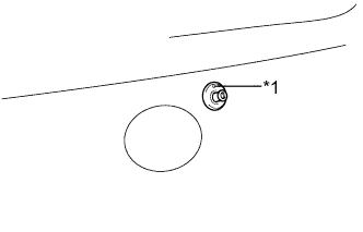
Install the rear wiper motor grommet with the position mark facing upward as shown in the illustration.
Text in Illustration *1 Position Mark
 |
| 11. INSTALL REAR WIPER MOTOR ASSEMBLY |
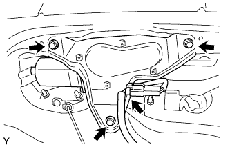
Install the wiper motor with the 3 bolts.
- Torque:
- 8.3 N*m{85 kgf*cm, 73 in.*lbf}
 |
Connect the connector.
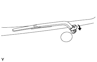
| 12. INSTALL REAR WIPER ARM AND BLADE ASSEMBLY |
Operate the rear wiper, and stop the rear wiper motor at the automatic stop position.
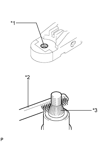
Clean the wiper pivot serration with a wire brush.
Text in Illustration *1 Wiper Arm Pivot Serrations *2 Wire Brush *3 Wiper Pivot Serrations
 |
Install the arm and blade with the nut. Make sure that the arm and blade comes to the position shown in the illustration.
- Torque:
- 8.4 N*m{86 kgf*cm, 74 in.*lbf}
- HINT:
- Hold down the arm hinge by hand while tightening the nut.
- Install the arm and blade so that the rear wiper blade is aligned with the ceramic line.
Text in Illustration *1 Ceramic Line
 |
Operate the rear wiper while spraying water or washer fluid on the glass. Ensure that there is no interference between the blade and pillar.
Close the wiper arm head cap.
 |
| 13. INSTALL REAR LIGHT ASSEMBLY LH |
Attach the rear light assembly LH with the claw and pin.
Install the 2 nuts to install the rear light assembly LH.
Connect the connector.
| 14. INSTALL REAR LIGHT ASSEMBLY RH |
- HINT:
- Use the same procedure described for the LH side.
| 15. INSTALL BACK DOOR OUTSIDE GARNISH |
Attach the 2 clips to install the back door outside garnish.
w/ Rear View Monitor System:
Install the nut.
w/o Rear View Monitor System:
Install the 3 nuts.
| 16. INSTALL REAR TELEVISION CAMERA ASSEMBLY (w/ Rear View Monitor System) |
Install the rear television camera assembly with the 2 nuts.
Connect the connector.
| 17. INSTALL BACK DOOR OUTSIDE HANDLE |
Install the back door outside handle with the 2 nuts.
| 18. INSTALL BACK DOOR LOCK ASSEMBLY |
Temporarily install the back door lock assembly with the 3 bolts.
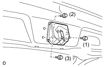 |
Tighten the bolts in the order shown in the illustration.
- Torque:
- 15 N*m{153 kgf*cm, 11 ft.*lbf}
Attach the back door lock cable assembly.
Connect the clamp and connect the connector.

Text in Illustration *1 Back Door Lock Cable Assembly - -
| 19. INSTALL BACK DOOR TRIM BOARD ASSEMBLY |
Attach the 16 clips to install the back door trim board.
| 20. INSTALL DOOR PULL HANDLE |
Attach the 4 claws to install the door pull handle.