Power Window Control System (For Lhd) Driver Side Power Window Does Not Operate With Power Window Master Switch
DESCRIPTION
WIRING DIAGRAM
INSPECTION PROCEDURE
INSPECT POWER WINDOW REGULATOR MOTOR ASSEMBLY
INSPECT POWER WINDOW REGULATOR MASTER SWITCH ASSEMBLY (for Driver Switch)
CHECK WIRE HARNESS (MASTER SWITCH - REGULATOR MOTOR)
POWER WINDOW CONTROL SYSTEM (for LHD) - Driver Side Power Window does not Operate with Power Window Master Switch |
DESCRIPTION
If the manual UP / DOWN and AUTO DOWN functions do not operate, a malfunction may be present in the power window regulator master switch, power window regulator motor or wire harness.
WIRING DIAGRAM
INSPECTION PROCEDURE
| 1.INSPECT POWER WINDOW REGULATOR MOTOR ASSEMBLY |
Remove the motor (Toyota Fortuner RM00000138V003X.html).
Apply battery voltage to connector terminals 1 and 2.
- NOTICE:
- Do not apply battery voltage to any terminals except terminals 1 and 2.
Check that the motor gear rotates smoothly as follows.
- OK:
Measurement Condition
| Specified Condition
|
Battery positive (+) → 1
Battery negative (-) → 2
| Motor gear rotates counterclockwise
|
Battery positive (+) → 2
Battery negative (-) → 1
| Motor gear rotates clockwise
|
| | REPLACE POWER WINDOW REGULATOR MOTOR ASSEMBLY |
|
|
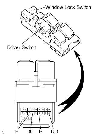
| 2.INSPECT POWER WINDOW REGULATOR MASTER SWITCH ASSEMBLY (for Driver Switch) |
Remove the master switch (Toyota Fortuner RM00000138V003X.html).
Measure the resistance of the switch when the switch is operated.
- Standard resistance:
Tester Connection
| Window Lock Switch Condition
| Driver Switch Condition
| Specified Condition
|
3 (E) - 9 (DD), 4 (DU) - 6 (B)
| Always
(ON / OFF)
| UP
| Below 1 Ω
|
3 (E) - 4 (DU), 3 (E) - 9 (DD)
| Always
(ON / OFF)
| OFF
| Below 1 Ω
|
3 (E) - 4 (DU), 6 (B) - 9 (DD)
| Always
(ON / OFF)
| DOWN
| Below 1 Ω
|
3 (E) - 4 (DU), 6 (B) - 9 (DD)
| Always
(ON / OFF)
| AUTO DOWN
| Below 1 Ω
|
| | REPLACE POWER WINDOW REGULATOR MASTER SWITCH ASSEMBLY |
|
|
| 3.CHECK WIRE HARNESS (MASTER SWITCH - REGULATOR MOTOR) |
Disconnect the P6 master switch connector.
Disconnect the P7 motor connector.
Measure the resistance of the wire harness side connectors.
- Standard resistance:
Tester Connection
| Specified Condition
|
P6-9 (DD) - P7-1
| Below 1 Ω
|
P6-4 (DU) - P7-2
| Below 1 Ω
|
P6-9 (DD) or P7-1 - Body ground
| 10 kΩ or higher
|
P6-4 (DU) or P7-2 - Body ground
| 10 kΩ or higher
|
| | REPAIR OR REPLACE HARNESS OR CONNECTOR |
|
|
| OK |
|
|
|
| GO TO POWER WINDOWS DO NOT OPERATE AT ALL |
|