Audio And Visual System (For Radio And Display Type) Parking Brake Switch Circuit
DESCRIPTION
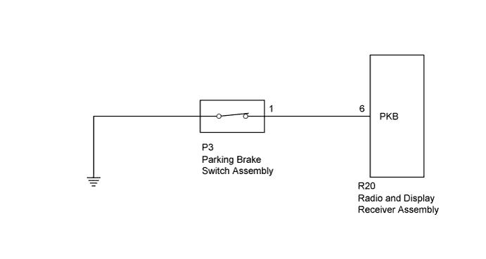
WIRING DIAGRAM
INSPECTION PROCEDURE
INSPECT PARKING BRAKE SWITCH ASSEMBLY
CHECK HARNESS AND CONNECTOR (RADIO AND DISPLAY RECEIVER - PARKING BRAKE SWITCH)
AUDIO AND VISUAL SYSTEM (for Radio and Display Type) - Parking Brake Switch Circuit |
DESCRIPTION
This circuit is from the parking brake switch assembly to the radio and display receiver assembly.
WIRING DIAGRAM
INSPECTION PROCEDURE
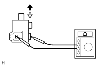
| 1.INSPECT PARKING BRAKE SWITCH ASSEMBLY |
Remove the parking brake switch assembly (Toyota Fortuner RM000001HKC008X.html).
Measure the resistance according to the value(s) in the table below.
- Standard Resistance:
Tester Connection
| Switch Condition
| Specified Condition
|
Switch connector - Switch body
| On (Shaft is not pressed)
| Below 1 Ω
|
Off (Shaft is pressed)
| 10 kΩ or higher
|
Text in Illustration
| On
|

| Off
|
| 2.CHECK HARNESS AND CONNECTOR (RADIO AND DISPLAY RECEIVER - PARKING BRAKE SWITCH) |
Disconnect the R20 radio and display receiver assembly connector.
Disconnect the P3 parking brake switch assembly connector.
Measure the resistance according to the value(s) in the table below.
- Standard Resistance:
Tester Connection
| Condition
| Specified Condition
|
R20-6 (PKB) - P3-1
| Always
| Below 1 Ω
|
R20-6 (PKB) - Body ground
| Always
| 10 kΩ or higher
|
| | REPAIR OR REPLACE HARNESS OR CONNECTOR |
|
|