Meter / Gauge System Fuel Gauge Malfunction
WIRING DIAGRAM
INSPECTION PROCEDURE
CHECK FUEL SUCTION WITH PUMP AND GAUGE TUBE ASSEMBLY (FUEL SENDER GAUGE)
CHECK WIRE HARNESS (METER - GAUGE)
METER / GAUGE SYSTEM - Fuel Gauge Malfunction |
WIRING DIAGRAM
INSPECTION PROCEDURE
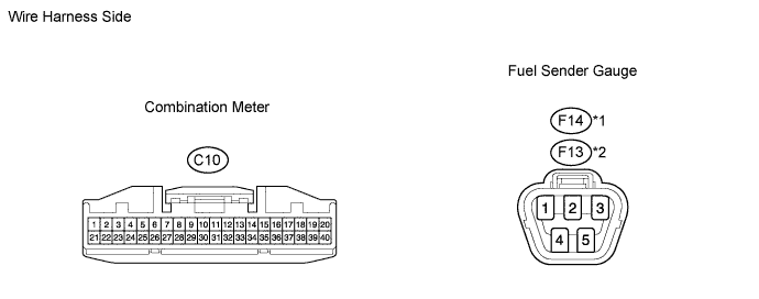
| 1.CHECK FUEL SUCTION WITH PUMP AND GAUGE TUBE ASSEMBLY (FUEL SENDER GAUGE) |
Disconnect the F14*1 or F13*2 pump and gauge connector.
- HINT:
- *1: 1GR-FE
- *2: 1KD-FTV
Turn the ignition switch ON, and then check the position of the receiver gauge needle.
- OK:
- Fuel receiver gauge indicates E.
Connect terminals 2 and 3 on the wire harness side connector.
Turn the ignition switch ON, and then check the position of the receiver gauge needle.
- OK:
- Fuel receiver gauge indicates F.
| | REPLACE FUEL SUCTION WITH PUMP AND GAUGE TUBE ASSEMBLY |
|
|
| 2.CHECK WIRE HARNESS (METER - GAUGE) |
Disconnect the C10 meter connector.
Disconnect the F14*1 or F13*2 pump and gauge connector.
- HINT:
- *1: 1GR-FE
- *2: 1KD-FTV
Measure the resistance of the wire harness side connectors.
- Standard resistance:
1GR-FETester Connection
| Specified Condition
|
C10-2 - F14-3
| Below 1 Ω
|
C10-3 - F14-2
|
- 1KD-FTV:
Tester Connection
| Specified Condition
|
C10-2 - F13-3
| Below 1 Ω
|
C10-3 - F13-2
|
| | REPAIR OR REPLACE HARNESS AND CONNECTOR |
|
|
| OK |
|
|
|
| REPLACE COMBINATION METER ASSEMBLY |
|