Meter / Gauge System -- Terminals Of Ecu |
| CHECK COMBINATION METER ASSEMBLY |
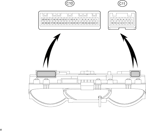
Disconnect the C10 and C11 meter connectors.
Measure the voltage and resistance according to the value(s) in the table below.
*1: for 1GR-FETerminal No. Wiring Color Terminal Description Condition Specified Condition C10-1 - Body ground R - Body ground Battery Always 11 to 14 V C10-21 - Body ground B-O - Body ground Ignition signal Ignition switch ON 11 to 14 V C10-21 - Body ground B-O - Body ground Ignition signal Ignition switch off Below 1 V C11-11 - Body ground*1 B-R - Body ground Power supply for fuel consumption calculation Ignition switch ON 11 to 14 V C11-11 - Body ground*1 B-R - Body ground Power supply for fuel consumption calculation Ignition switch off Below 1 V C10-22 - Body ground Y - Body ground Ground Always Below 1 Ω C10-19 - Body ground*2 W-B - Body ground Ground Always Below 1 Ω C10-38 - Body ground*3 R-G - Body ground Ground Always Below 1 Ω C10-9 - Body ground*4 W-B - Body ground Rheostat signal Rheostat knob fully turned to left position 702 Ω C10-9 - Body ground*4 W-B - Body ground Rheostat signal Rheostat knob fully turned to right position Below 1 Ω C10-9 - Body ground*5 W-G - Body ground Ground Always Below 1 Ω C10-26 - Body ground*6 W-B - Body ground Ground Always Below 1 Ω
*2: w/o Airbag System
*3: w/o ABS
*4: w/ Light Control Rheostat
*5: w/o Light Control Rheostat
*6: w/o VSC
If the result is not as specified, there may be a malfunction on the wire harness side.Reconnect the C10 and C11 meter connectors.
Measure the voltage according to the value(s) in the table below.
*1: for 1GR-FETerminal No. Wiring Color Terminal Description Condition Specified Condition C10-2 - C10-3 BR - BR-Y Fuel level signal Ignition switch ON, fuel level F Below 1 V C10-2 - C10-3 BR - BR-Y Fuel level signal Ignition switch ON, fuel level E 4 to 7 V C10-5 - Body ground P-L - Body ground Vehicle speed signal (input) Driving at approximately 20 km/h (12.4 mph) Waveform 1 C10-6 - Body ground V-R - Body ground Vehicle speed signal (output) Driving at approximately 20 km/h (12.4 mph) Waveform 1 C10-7 - Body ground B-W - Body ground Tachometer signal Engine idling Waveform 2 C10-8 - Body ground G - Body ground Light control switch signal Light control switch is HEAD or TAIL 11 to 14 V C10-8 - Body ground G - Body ground Light control switch signal Light control switch is off Below 1 V C10-10 - Body ground G-Y - Body ground Unlock warning switch signal Ignition switch off, key is in ignition key cylinder 11 to 14 V C10-10 - Body ground G-Y - Body ground Unlock warning switch signal No key in ignition key cylinder Below 1 V C10-11 - Body ground R-Y - Body ground Driver side seat belt warning signal Ignition switch ON, driver side seat belt fastened 11 to 14 V C10-11 - Body ground R-Y - Body ground Driver side seat belt warning signal Ignition switch ON, driver side seat belt unfastened Below 1 V C10-12 - C10-13*1 G-B - W-G A/T P warning light signal Ignition switch ON, shift lever on P, A/T P warning light ON 11 to 14 V C10-12 - C10-13*1 G-B - W-G A/T P warning light signal Ignition switch ON, shift lever on P, A/T P warning light OFF Below 1 V C10-14 - Body ground*2 W-G - Body ground FUEL FILTER warning light signal Ignition switch ON, FUEL FILTER warning light OFF 11 to 14 V C10-14 - Body ground*2 W-G - Body ground FUEL FILTER warning light signal Ignition switch ON, FUEL FILTER warning light ON Below 1 V C10-15 - Body ground R-B - Body ground Driver side door signal (output) Driver side door is open 11 to 14 V C10-15 - Body ground R-B - Body ground Driver side door signal (output) Driver side door is closed Below 1 V C10-16 - Body ground R-B - Body ground Driver side door signal (input) Driver side door is open 11 to 14 V C10-16 - Body ground R-B - Body ground Driver side door signal (input) Driver side door is closed Below 1 V C10-17 - Body ground R-L - Body ground Door signal Doors open (Disregarding driver side door) 11 to 14 V C10-17 - Body ground R-L - Body ground Door signal Doors closed (Disregarding driver side door) Below 1 V C10-18 - Body ground*1 P - Body ground A/T OIL TEMP warning light signal Ignition switch ON, A/T OIL TEMP warning light OFF 11 to 14 V C10-18 - Body ground*1 P - Body ground A/T OIL TEMP warning light signal Ignition switch ON, A/T OIL TEMP warning light ON Below 1 V C10-20 - Body ground*3 B-Y - Body ground SRS warning light signal Ignition switch ON, SRS warning light OFF Waveform 3 C10-20 - Body ground*3 B-Y - Body ground SRS warning light signal Ignition switch ON, SRS warning light ON Waveform 4 C10-23 - Body ground*2 L-R - Body ground FUEL FILTER warning light signal Ignition switch ON, FUEL FILTER warning light OFF 11 to 14 V C10-23 - Body ground*2 L-R - Body ground FUEL FILTER warning light signal Ignition switch ON, FUEL FILTER warning light ON Below 1 V C10-24 - Body ground G-B - Body ground Turn signal indicator LH signal Ignition switch ON, turn signal indicator LH light ON 11 to 14 V C10-24 - Body ground G-B - Body ground Turn signal indicator LH signal Ignition switch ON, turn signal indicator LH light OFF Below 1 V C10-25 - Body ground G-Y - Body ground Turn signal indicator RH signal Ignition switch ON, turn signal indicator RH light ON 11 to 14 V C10-25 - Body ground G-Y - Body ground Turn signal indicator RH signal Ignition switch ON, turn signal indicator RH light OFF Below 1 V C10-26 - Body ground*4 LG - Body ground BRAKE indicator light signal Ignition switch ON, BRAKE indicator light OFF 11 to 14 V C10-26 - Body ground*4 LG - Body ground BRAKE indicator light signal Ignition switch ON, BRAKE indicator light ON Below 1 V C10-27 - Body ground R-Y - Body ground HIGH BEAM indicator signal HIGH BEAM indicator light OFF 11 to 14 V C10-27 - Body ground R-Y - Body ground HIGH BEAM indicator signal HIGH BEAM indicator light ON Below 1 V C10-28 - Body ground*5 L-B - Body ground CRUISE indicator light signal Ignition switch ON, CRUISE indicator light OFF 11 to 14 V C10-28 - Body ground*5 L-B - Body ground CRUISE indicator light signal Ignition switch ON, CRUISE indicator light ON Below 1 V C10-30 - Body ground*6 G-B - Body ground FR FOG indicator light signal Light control switch TAIL or HEAD, fog light switch off 11 to 14 V C10-30 - Body ground*6 G-B - Body ground FR FOG indicator light signal Light control switch TAIL or HEAD, fog light switch on Below 1 V C10-31 - Body ground R-B - Body ground CENTER DIFFERENTIAL LOCK indicator light signal Ignition switch ON, CENTER DIFFERENTIAL LOCK indicator light OFF 11 to 14 V C10-31 - Body ground R-B - Body ground CENTER DIFFERENTIAL LOCK indicator light signal Ignition switch ON, CENTER DIFFERENTIAL LOCK indicator light ON Below 1 V C10-33 - Body ground B - Body ground REAR DIFFERENTIAL LOCK indicator light signal Ignition switch ON, REAR DIFFERENTIAL LOCK indicator light OFF 11 to 14 V C10-33 - Body ground B - Body ground REAR DIFFERENTIAL LOCK indicator light signal Ignition switch ON, REAR DIFFERENTIAL LOCK indicator light OFF Below 1 V C10-34 - Body ground*7 W - Body ground Engine oil level sensor signal Ignition switch ON, OIL LEVEL warning light OFF 11 to 14 V C10-34 - Body ground*7 W - Body ground Engine oil level sensor signal Ignition switch ON, OIL LEVEL warning light ON Below 1 V C10-35 - Body ground LG-B - Body ground OIL PRESSURE warning light signal Ignition switch ON, OIL PRESSURE warning light OFF 11 to 14 V C10-35 - Body ground LG-B - Body ground OIL PRESSURE warning light signal Ignition switch ON, OIL PRESSURE warning light ON Below 1 V C10-36 - Body ground LG - Body ground BRAKE warning light signal Ignition switch ON, BRAKE warning light OFF 11 to 14 V C10-36 - Body ground LG - Body ground BRAKE warning light signal Ignition switch ON, BRAKE warning light ON Below 1 V C10-37 - Body ground GR - Body ground CHARGE warning light signal Ignition switch ON, CHARGE warning light OFF 11 to 14 V C10-37 - Body ground GR - Body ground CHARGE warning light signal Ignition switch ON, CHARGE warning light ON Below 1 V C10-38 - Body ground*8 R-G - Body ground ABS warning light signal Ignition switch ON, ABS warning light OFF 11 to 14 V C10-38 - Body ground*8 R-G - Body ground ABS warning light signal Ignition switch ON, ABS warning light ON Below 1 V C10-39 - Body ground R-B - Body ground MIL signal Ignition switch ON, MIL OFF 11 to 14 V C10-39 - Body ground R-B - Body ground MIL signal Ignition switch ON, MIL ON Below 1 V C10-40 - Body ground*2 Y-R - Body ground GLOW indicator light signal Ignition switch ON, GLOW indicator light OFF 11 to 14 V C10-40 - Body ground*2 Y-R - Body ground GLOW indicator light signal Ignition switch ON, GLOW indicator light ON Below 1 V C11-1 - Body ground*9 GR-L - Body ground Automatic transmission shift position signal (L) Ignition switch ON, automatic transmission L indicator light ON 11 to 14 V C11-1 - Body ground*9 GR-L - Body ground Automatic transmission shift position signal (L) Ignition switch ON, automatic transmission L indicator light OFF Below 1 V C11-2 - Body ground*9 P-L - Body ground Automatic transmission shift position signal (2) Ignition switch ON, automatic transmission 2 indicator light ON 11 to 14 V C11-2 - Body ground*9 P-L - Body ground Automatic transmission shift position signal (2) Ignition switch ON, automatic transmission 2 indicator light OFF Below 1 V C11-3 - Body ground*9 L - Body ground Automatic transmission shift position signal (3) Ignition switch ON, automatic transmission 3 indicator light ON 11 to 14 V C11-3 - Body ground*9 L - Body ground Automatic transmission shift position signal (3) Ignition switch ON, automatic transmission 3 indicator light OFF Below 1 V C11-4 - Body ground*9 G-O - Body ground Automatic transmission shift position signal (4) Ignition switch ON, automatic transmission 4 indicator light ON 11 to 14 V C11-4 - Body ground*9 G-O - Body ground Automatic transmission shift position signal (4) Ignition switch ON, automatic transmission 4 indicator light OFF Below 1 V C11-5 - Body ground*9 B-R - Body ground Automatic transmission shift position signal (D) Ignition switch ON, automatic transmission D indicator light ON 11 to 14 V C11-5 - Body ground*9 B-R - Body ground Automatic transmission shift position signal (D) Ignition switch ON, automatic transmission D indicator light OFF Below 1 V C11-6 - Body ground*9 R-W - Body ground Automatic transmission shift position signal (N) Ignition switch ON, automatic transmission N indicator light ON 11 to 14 V C11-6 - Body ground*9 R-W - Body ground Automatic transmission shift position signal (N) Ignition switch ON, automatic transmission N indicator light OFF Below 1 V C11-9 - Body ground*7 G-B - Body ground Signal for amount of fuel consumption Engine idling Pulse generation C11-10 - Body ground*1 L - Body ground Injector signal Engine idling Pulse generation C11-14 - Body ground*9 R-Y - Body ground Automatic transmission shift position signal (R) Ignition switch ON, automatic transmission R indicator light ON 11 to 14 V C11-14 - Body ground*9 R-Y - Body ground Automatic transmission shift position signal (R) Ignition switch ON, automatic transmission R indicator light OFF Below 1 V C11-15 - Body ground*4 BR - Body ground VSC OFF indicator light signal Ignition switch ON, VSC OFF indicator light OFF 11 to 14 V C11-15 - Body ground*4 BR - Body ground VSC OFF indicator light signal Ignition switch ON, VSC OFF indicator light ON Below 1 V C11-16 - Body ground*4 P - Body ground SLIP indicator light signal Ignition switch ON, SLIP indicator light OFF 11 to 14 V C11-16 - Body ground*4 P - Body ground SLIP indicator light signal Ignition switch ON, SLIP indicator light ON Below 1 V
*2: for 1KD-FTV, 5L-E
*3: w/ Airbag System
*4: w/ VSC
*5: w/ Cruise Control System
*6: w/ Fog Light
*7: for 1KD-FTV
*8: w/ ABS
*9: w/ Automatic Transmission Shift Indicator Light
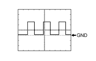
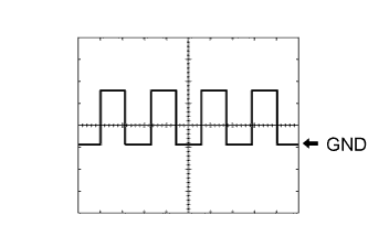
If the result is not as specified, the combination meter may be malfunctioning.Using an oscilloscope, check waveform 1.
Measurement Condition Item Content Terminal No. - C10-5 - Body ground
- C10-6 - Body ground
Tool Setting 5 V/DIV., 10 msec./DIV. Vehicle Condition Driving at approximately 20 km/h (12.4 mph) - HINT:
- As the vehicle speed increases, the wavelength shortens.
- C10-5 - Body ground
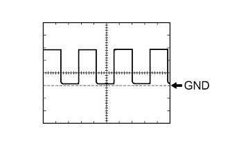
Using an oscilloscope, check waveform 2.
Measurement Condition Item Content Terminal No. C10-7 - Body ground Tool Setting 5 V/DIV., 10 msec./DIV. Vehicle Condition Engine idling - HINT:
- As the engine speed increases, the wavelength shortens.
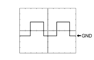
Using an oscilloscope, check waveform 3.
Measurement Condition Item Content Terminal No. C10-20 - Body ground Tool Setting 5 V/DIV., 50 msec./DIV. Vehicle Condition Ignition switch ON, SRS warning light OFF Using an oscilloscope, check waveform 4.
Measurement Condition Item Content Terminal No. C10-20 - Body ground Tool Setting 5 V/DIV., 50 msec./DIV. Vehicle Condition Ignition switch ON, SRS warning light ON
| CHECK MULTI-DISPLAY |

Disconnect the A23 multi-display connector.
Measure the voltage and resistance according to the value(s) in the table below.
If the result is not as specified, there may be a malfunction on the wire harness side.Terminal No. (Symbols) Wiring Color Terminal Description Condition Specified Condition A23-14 (+B) - Body ground R - Body ground +B power supply Always 11 to 14 V A23-12 (IG) - Body ground R-B - Body ground IG power supply Ignition switch ON 11 to 14 V A23-12 (IG) - Body ground R-B - Body ground IG power supply Ignition switch off Below 1 V A23-13 (ACC) - Body ground G-R - Body ground ACC power supply Ignition switch ACC 11 to 14 V A23-13 (ACC) - Body ground G-R - Body ground ACC power supply Ignition switch off Below 1 V A23-1 (GND1) - Body ground LG - Body ground Ground Always Below 1 Ω A23-10 (SGND) - Body ground BR - Body ground Ground Always Below 1 Ω Reconnect the A23 multi-display connector.
Measure the voltage according to the value(s) in the table below.
*1: for Automatic Air Conditioning SystemTerminal No. (Symbols) Wiring Color Terminal Description Condition Specified Condition A23-2 (SG) - A23-3 (TH+)*1 BR-Y - W-G Air conditioning ambient temperature sensor signal Ignition switch ON, ambient temperature 25°C (77°F) 1.35 to 1.75 V A23-2 (SG) - A23-3 (TH+)*1 BR-Y - W-G Air conditioning ambient temperature sensor signal Ignition switch ON, ambient temperature 40°C (104°F) 0.85 to 2.34 V A23-11 (SW+) - Body ground*2 B - Body ground Steering pad switch signal Ignition switch ON, steering pad switch not pressed 4 V or more A23-11 (SW+) - Body ground*2 B - Body ground Steering pad switch signal Ignition switch ON, INFO switch pressed Below 1 V A23-11 (SW+) - Body ground*2 B - Body ground Steering pad switch signal Ignition switch ON, MODE RESET switch pressed 2 to 3 V A23-8 (PBEW) - Body ground*3 G-W - Body ground Front passenger side seat belt warning light signal Ignition switch ON, front passenger side seat belt warning light OFF 11 to 14 V A23-8 (PBEW) - Body ground*3 G-W - Body ground Front passenger side seat belt warning light signal Ignition switch ON, front passenger side seat belt warning light ON Below 1 V
*2: w/ Steering Pad Switch
*3: w/ Front Passenger Seat Belt Warning System
If the result is not as specified, the accessory meter may be malfunctioning.
| COMBINATION METER INNER CIRCUIT |
*2: for 1KD-FTV, 5L-E
*3: for 1KD-FTV
*4: w/ Airbag System
*5: w/o Airbag System
*6: w/ Multi-display
*7: for 2TR-FE, 1KD-FTV, 5L-E
*8: w/ Fog Light
*9: w/ Automatic Transmission Shift Indicator Light
*10: w/ Cruise Control System
*11: w/ Rear Differential Lock System
*12: w/ VSC


| TABLE OF TERMINAL CONNECTION |
*2: w/o Light Control Rheostat
*3: for 1GR-FE
*4: for 1KD-FTV, 5L-E
*5: w/o Airbag System
*6: w/ Airbag System
*7: w/ VSC
*8: w/o VSC
*9: w/ Cruise Control System
*10: w/ Fog Light
*11: w/ Rear Differential Lock System
*12: for 1KD-FTV
*13: w/ ABS
*14: w/o ABS
*15: w/ Automatic Transmission Shift Indicator Light
*16: w/ Multi-display
| Terminal No. | Wire Harness Side | |
| C10 | 1 | DOME fuse |
| 2 | Fuel sender gauge | |
| 3 | Fuel sender gauge | |
| 4 | ECM | |
| 5 | Vehicle speed sensor | |
| 6 | 4-pulse output | |
| 7 | ECM | |
| 8 | Headlight dimmer switch | |
| 9 |
| |
| 10 | Unlock warning switch | |
| 11 | Front seat inner belt (for Driver Side) | |
| 12 | Park / neutral position switch*3 | |
| 13 | Transfer neutral detection switch*3 | |
| 14 | Fuel filter (Fuel filter switch)*4 | |
| 15 | Integration relay | |
| 16 | Front door courtesy switch (for Driver Side) | |
| 17 |
| |
| 18 | ECM*3 | |
| 19 | Body ground*5 | |
| 20 | Center airbag sensor assembly*6 | |
| 21 | MET fuse | |
| 22 | Body ground | |
| 23 | Fuel filter (Fuel sedimenter switch)*4 | |
| 24 | Turn signal flasher relay | |
| 25 | Turn signal flasher relay | |
| 26 |
| |
| 27 | Headlight dimmer switch | |
| 28 | ECM*9 | |
| 29 | - | |
| 30 | Fog light switch*10 | |
| 31 | Transfer indicator switch | |
| 32 | - | |
| 33 | Four wheel drive control ECU*11 | |
| 34 | Engine oil level sensor*12 | |
| 35 | Engine oil pressure switch | |
| 36 |
| |
| 37 | Generator | |
| 38 |
| |
| 39 | ECM | |
| 40 | ECM*4 | |
| C11 | 1 | Shift lock control ECU*15 |
| 2 | Shift lock control ECU*15 | |
| 3 | Park / neutral position switch*15 | |
| 4 | Shift lock control ECU*15 | |
| 5 | Shift lock control ECU*15 | |
| 6 | Park / neutral position switch*15 | |
| 7 | - | |
| 8 | - | |
| 9 | ECM*12 | |
| 10 | No. 1 fuel Injector*3 | |
| 11 | INJ fuse*3 | |
| 12 | Multi-display*16 | |
| 13 | Multi-display*16 | |
| 14 | Park / neutral position switch*15 | |
| 15 | - | |
| 16 | - | |