Wireless Door Lock Control System (For Built-In Type Door Control Receiver) -- Terminals Of Ecu |
| CHECK THEFT WARNING ECU |

Disconnect the T16 ECU connector.
Measure the resistance and voltage of the wire harness side connector.
Symbols (Terminal No.) Wiring Color Terminal Description Condition Specified Condition E (T16-1) - Body ground W-B - Body ground Ground Always Below 1 Ω IG (T16-4) - E (T16-1) R-L - B-W Ignition power supply Ignition switch OFF Below 1 V Ignition switch ON 10 to 14 V +B1 (T16-3) - E (T16-1) L-Y - B-W +B (ECU-B) power source Always 10 to 14 V +B2 (T16-12) - E (T16-1) LG - B-W +B (DOOR) power source Always 10 to 14 V L2 (T16-20) - Body ground L - Body ground Door control switch (master switch) lock output Door control switch (master switch) LOCK 10 kΩ or higher Door control switch (master switch) OFF Below 1 Ω UL3 (T16-21) -Body ground L-W - Body ground Door control switch (master switch) unlock output Door control switch UNLOCK 10 kΩ or higher Door control switch OFF Below 1 Ω CTY (T16-7) - Body ground R-L - Body ground All door courtesy switches except driver side door All doors are closed except driver side door 10 kΩ or higher One or more doors are open except driver side door Below 1 Ω KSW (T16-5) - Body ground G-Y - Body ground Unlock warning switch No key in ignition key cylinder 10 kΩ or higher Key inserted in ignition key cylinder Below 1 Ω - If the result is not as specified, there may be a malfunction on the wire harness side.
- If the result is not as specified, there may be a malfunction on the wire harness side.
Reconnect the T16 ECU connector.
Measure the voltage of the connector.
Symbols (Terminal No.) Wiring Color Terminal Description Condition Specified Condition HAZD (T16-23) - Body ground G-O -Body ground Hazard warning lights signal output Hazard warning lights OFF Below 1 V Hazard warning lights ON Pulse generation SH- (T16-26) - Body ground B - Body ground Security horn signal output Security horn OFF Below 1 V Security horn ON Pulse generation - If the result is not as specified, the ECU may have a malfunction.
- If the result is not as specified, the ECU may have a malfunction.
| CHECK INSTRUMENT PANEL JUNCTION BLOCK (INTEGRATION RELAY) |
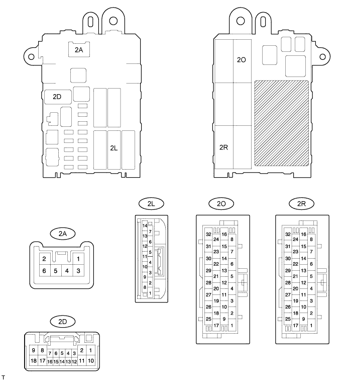
Disconnect the 2A, 2D, 2L and 2O junction block connectors.
Measure the voltage and resistance of the wire harness side connectors.
Symbols (Terminal No.) Wiring Color Terminal Description Condition Specified Condition GND (2D-9) - Body ground W-B - Body ground Ground Always Below 1 Ω BECU (2L-12) - GND (2D-9) L - W-B +B (ECU - B) power source Always 10 to 14 V L1 (2A-4) - Body ground L - Body ground Door control switch (master switch) lock input Door control switch (master switch) LOCK 10 kΩ or higher Door control switch (master switch) OFF Below 1 Ω UL1 (2D-4) - Body ground L-W - Body ground Door control switch (master switch) unlock input Door control switch (master switch) UNLOCK 10 kΩ or higher Door control switch (master switch) OFF Below 1 Ω DCTY (2O-27) - Body ground R-B - Body ground Driver side door courtesy switch Driver side door closed 10 kΩ or higher Driver side door open Below 1 Ω - If the result is not as specified, there may be a malfunction on the wire harness side.
- If the result is not as specified, there may be a malfunction on the wire harness side.
Reconnect the 2A, 2D, 2L and 2O junction block connectors.
Measure the voltage of the wire harness side connectors.
Symbols (Terminal No.) Wiring Color Terminal Description Condition Specified Condition ACT+ (2R-28) - Body ground L - Body ground Door lock motor LOCK drive output (driver side door) Door control switch (master switch) or driver side door key cylinder OFF Below 1 V Door control switch (master switch) or driver side door key cylinder LOCK 10 to 14 V ACT- (2R-27) - Body ground L-Y - Body ground Door lock motor UNLOCK drive output (driver side door) Door control switch (master switch) or driver side door key cylinder OFF Below 1 V Door control switch (master switch) or driver side door key cylinder UNLOCK 10 to 14 V - If the result is not as specified, the junction block (relay) may have a malfunction.
- If the result is not as specified, the junction block (relay) may have a malfunction.