Power Door Lock Control System (W/ Theft Deterrent System) -- Terminals Of Ecu |
| CHECK INSTRUMENT PANEL JUNCTION BLOCK (INTEGRATION RELAY) |
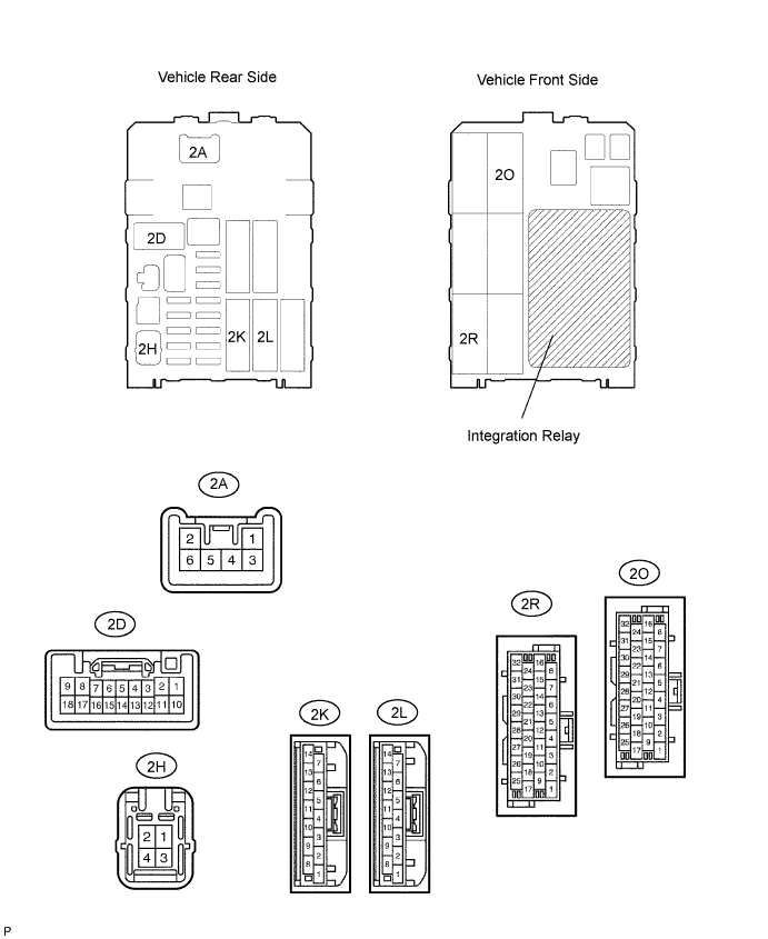
Disconnect the 2A, 2D, 2H and 2L junction block connectors.
Measure the voltage and resistance of the wire harness side connectors.
Symbols (Terminal No.) Wiring Color Terminal Description Condition Specified Condition BECU (2L-12) - Body ground L - Body ground +B (BECU) power supply Always 10 to 14 V ALTB (2H-4) - Body ground LG - Body ground +B (power system, generator system) power supply Always 10 to 14 V GND (2D-9, 18) - Body ground W-B - Body ground Ground Always Below 1 Ω L1 (2A-4) - Body ground L - Body ground Door control switch lock input Door control switch OFF 10 kΩ or higher L1 (2A-4) - Body ground L - Body ground Door control switch lock input Door control switch LOCK Below 1 Ω UL1 (2D-4) - Body ground L-W - Body ground Door control switch unlock input Door control switch OFF 10 kΩ or higher UL1 (2D-4) - Body ground L-W - Body ground Door control switch unlock input Door control switch UNLOCK Below 1 Ω - If the result is not as specified, there may be a malfunction on the wire harness side.
- If the result is not as specified, there may be a malfunction on the wire harness side.
Reconnect the 2A, 2D, 2H and 2L junction block connectors.
Measure the voltage of the connectors.
| Symbols (Terminal No.) | Wiring Color | Terminal Description | Condition | Specified Condition |
| ACT+ (2R-28) - Body ground | L - Body ground | Door lock motor LOCK drive output (driver door and rear LH door)*1 | Door control switch or driver door key cylinder OFF | Below 1 V |
| Door lock motor LOCK drive output (driver door and rear RH door)*2 | ||||
| ACT+ (2R-28) - Body ground | L - Body ground | Door lock motor LOCK drive output (driver door and rear LH door)*1 | Door control switch or driver door key cylinder LOCK | 10 to 14 V |
| Door lock motor LOCK drive output (driver door and rear RH door)*2 | ||||
| ACT+ (2K-11) - Body ground | L - Body ground | Door lock motor LOCK drive output (passenger door, rear RH door and back door)*1 | Door control switch or driver door key cylinder OFF | Below 1 V |
| Door lock motor LOCK drive output (passenger door, rear LH door and back door)*2 | ||||
| ACT+ (2K-11) - Body ground | L - Body ground | Door lock motor LOCK drive output (passenger door, rear RH door and back door)*1 | Door control switch or driver door key cylinder LOCK | 10 to 14 V |
| Door lock motor LOCK drive output (passenger door, rear LH door and back door)*2 | ||||
| ACT- (2R-27) - Body ground | L-Y - Body ground | Door lock motor UNLOCK drive output (driver door and rear LH door)*1 | Door control switch or driver door key cylinder OFF | Below 1 V |
| Door lock motor UNLOCK drive output (driver door and rear RH door)*2 | ||||
| ACT- (2R-27) - Body ground | L-Y - Body ground | Door lock motor UNLOCK drive output (driver door and rear LH door)*1 | Door control switch or driver door key cylinder UNLOCK | 10 to 14 V |
| Door lock motor UNLOCK drive output (driver door and rear RH door)*2 | ||||
| ACT- (2K-10) - Body ground | L-Y - Body ground | Door lock motor UNLOCK drive output (passenger door, rear RH door and back door)*1 | Door control switch or driver door key cylinder OFF | Below 1 V |
| Door lock motor UNLOCK drive output (passenger door, rear LH door and back door)*2 | ||||
| ACT- (2K-10) - Body ground | L-Y - Body ground | Door lock motor UNLOCK drive output (passenger door, rear RH door and back door)*1 | Door control switch or driver door key cylinder UNLOCK | 10 to 14 V |
| Door lock motor UNLOCK drive output (passenger door, rear LH door and back door)*2 | ||||
| DCTY (2O-27) - Body ground | R-B - Body ground | Driver side courtesy switch input | Driver side door closed | Below 1 V |
| DCTY (2O-27) - Body ground | R-B - Body ground | Driver side courtesy switch input | Driver side door open | 10 to 14 V |
- HINT:
- *1: for LHD
- *2: for RHD
- If the result is not as specified, the junction block relay (integration relay) may have a malfunction.
| CHECK THEFT WARNING ECU |

Disconnect the T16 ECU connector.
Measure the resistance of the wire harness side connector.
If the result is not as specified, there may be a malfunction on the wire harness side.Symbols (Terminal No.) Wiring Color Terminal Description Specified Condition E (T16-1) - Body ground W-B - Body ground Ground Below 1 Ω Reconnect the T16 ECU connector.
Measure the voltage of the connector.
If the result is not as specified, the theft warning ECU may have a malfunction.Symbols (Terminal No.) Wiring Color Terminal Description Condition Specified Condition DDUL (T16-11) - Body ground L-Y - Body ground Door lock motor UNLOCK drive output (driver door) Door control switch or driver door key cylinder OFF Below 1 V DDUL (T16-11) - Body ground L-Y - Body ground Door lock motor UNLOCK drive output (driver door) Door control switch or driver door key cylinder UNLOCK 10 to 14 V