Lighting System Lvl Terminal Circuit
DESCRIPTION
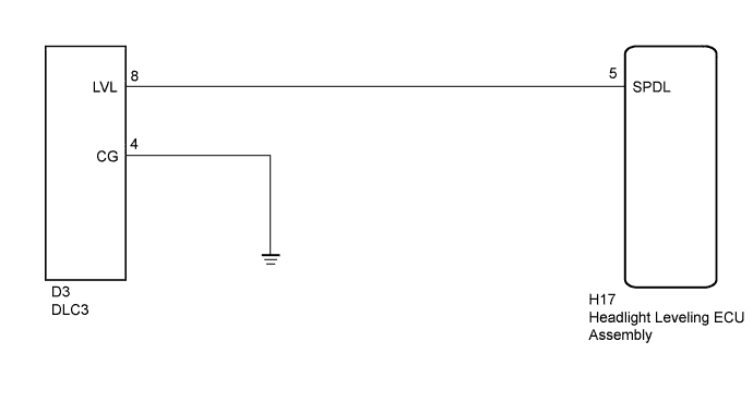
WIRING DIAGRAM
INSPECTION PROCEDURE
CHECK HARNESS AND CONNECTOR (DLC3 - HEADLIGHT LEVELING ECU ASSEMBLY)
CHECK HARNESS AND CONNECTOR (DLC3 - BODY GROUND)
LIGHTING SYSTEM - LVL Terminal Circuit |
DESCRIPTION
- When terminals LVL and CG of the DLC3 are connected, the headlight leveling ECU initializes the height control sensor signal.
WIRING DIAGRAM
INSPECTION PROCEDURE
- HINT:
- After replacing the headlight leveling ECU, initialization of the ECU is necessary (Toyota Fortuner RM000002CE402CX.html).
| 1.CHECK HARNESS AND CONNECTOR (DLC3 - HEADLIGHT LEVELING ECU ASSEMBLY) |
Disconnect the H17 headlight leveling ECU connector.
Measure the resistance according to the value(s) in the table below.
- Standard Resistance:
Tester Connection
| Condition
| Specified Condition
|
H17-5 (SPDL) - D3-8 (LVL)
| Always
| Below 1 Ω
|
H17-5 (SPDL) - Body ground
| Always
| 10 kΩ or higher
|
| | REPAIR OR REPLACE HARNESS OR CONNECTOR |
|
|
| 2.CHECK HARNESS AND CONNECTOR (DLC3 - BODY GROUND) |
Measure the resistance according to the value(s) in the table below.
- Standard Resistance:
Tester Connection
| Condition
| Specified Condition
|
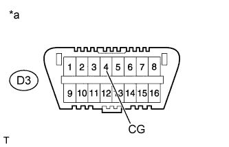
D3-4 (CG) - Body ground
| Always
| Below 1 Ω
|
Text in Illustration*a
| Front view of DLC3
|
| | REPAIR OR REPLACE HARNESS OR CONNECTOR |
|
|