Cruise Control System Cruise Main Indicator Light Circuit
DESCRIPTION
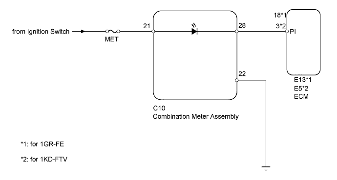
WIRING DIAGRAM
INSPECTION PROCEDURE
INSPECT FUSE (MET)
CHECK HARNESS AND CONNECTOR (COMBINATION METER - ECM, BATTERY AND BODY GROUND)
CRUISE CONTROL SYSTEM - Cruise Main Indicator Light Circuit |
DESCRIPTION
When the cruise control main switch is turned on, the CRUISE main indicator light illuminates.
WIRING DIAGRAM
INSPECTION PROCEDURE
Disconnect the MET fuse from the driver side junction block.
Measure the resistance according to the value(s) in the table below.
- Standard Resistance:
Tester Connection
| Condition
| Specified Condition
|
MET fuse
| Always
| Below 1 Ω
|
| 2.CHECK HARNESS AND CONNECTOR (COMBINATION METER - ECM, BATTERY AND BODY GROUND) |
Disconnect the C10 meter connector.
Disconnect the E13*1 or E5*2 ECM connector.
- *1: for 1GR-FE
- *2: for 1KD-FTV
Measure the voltage and resistance according to the value(s) in the table below.
- Standard Voltage:
Tester Connection
| Switch Condition
| Specified Condition
|
C10-21 - Body ground
| Ignition switch ON
| 11 to 14 V
|
C10-21 - Body ground
| Ignition switch off
| Below 1 V
|
- Standard Resistance:
- for 1GR-FE:
Tester Connection
| Condition
| Specified Condition
|
C10-28 - E13-18 (PI)
| Always
| Below 1 Ω
|
C10-28 - Body ground
| Always
| 10 kΩ or higher
|
C10-22 - Body ground
| Always
| Below 1 Ω
|
- for 1KD-FTV:
Tester Connection
| Condition
| Specified Condition
|
C10-28 - E5-3 (PI)
| Always
| Below 1 Ω
|
C10-28 - Body ground
| Always
| 10 kΩ or higher
|
C10-22 - Body ground
| Always
| Below 1 Ω
|
| | REPAIR OR REPLACE HARNESS OR CONNECTOR |
|
|
| OK |
|
|
|
| REPLACE COMBINATION METER ASSEMBLY |
|