Cruise Control System Cruise Main Indicator Light Circuit
DESCRIPTION
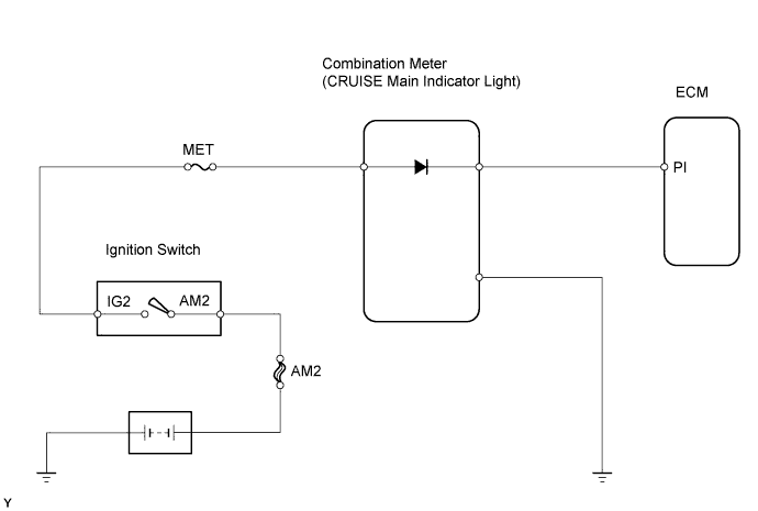
WIRING DIAGRAM
INSPECTION PROCEDURE
PERFORM ACTIVE TEST USING INTELLIGENT TESTER (CRUISE MAIN INDICATOR LIGHT)
INSPECT FUSE (MET)
CHECK WIRE HARNESS (COMBINATION METER - ECM, BATTERY AND BODY GROUND)
CRUISE CONTROL SYSTEM - Cruise Main Indicator Light Circuit |
DESCRIPTION
When the cruise control main switch is turned ON, the CRUISE main indicator light illuminates.
WIRING DIAGRAM
INSPECTION PROCEDURE
| 1.PERFORM ACTIVE TEST USING INTELLIGENT TESTER (CRUISE MAIN INDICATOR LIGHT) |
Select the Active Test, use the intelligent tester to generate a control command, and then check that the CRUISE main indicator light illuminates.
Combination meter assembly:Item
| Test Details
| Diagnostic Note
|
Indicator Light Cruise
| CRUISE main indicator light is ON/OFF
| -
|
- OK:
- Cruise main indicator light turns ON/OFF.
| | PROCEED TO NEXT CIRCUIT INSPECTION SHOWN IN PROBLEM SYMPTOMS TABLE |
|
|
Remove the MET fuse from the instrument panel junction block.
Measure the resistance of the fuse.
- Standard resistance:
- Below 1 Ω
| 3.CHECK WIRE HARNESS (COMBINATION METER - ECM, BATTERY AND BODY GROUND) |
Disconnect the C10 meter connector.
Disconnect the E13 ECM connector.
Measure the voltage and resistance of the wire harness side connectors.
- Standard voltage:
Tester Connection
| Switch Condition
| Specified Condition
|
C10-21 - Body ground
| Ignition switch ON
| 10 to 14 V
|
C10-21 - Body ground
| Ignition switch OFF
| Below 1 V
|
- Standard resistance:
Tester Connection
| Switch Condition
| Specified Condition
|
C10-28 - E13-18 (PI)
| Always
| Below 1 Ω
|
C10-28 - Body ground
| Always
| 10 kΩ or higher
|
C10-22 - Body ground
| Always
| Below 1 Ω
|
| | REPAIR OR REPLACE HARNESS AND CONNECTOR |
|
|
| OK |
|
|
|
| REPLACE COMBINATION METER ASSEMBLY |
|