Theft Deterrent System Ecu Power Source Circuit
DESCRIPTION
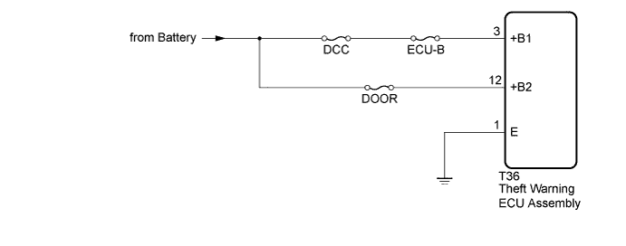
WIRING DIAGRAM
INSPECTION PROCEDURE
CHECK HARNESS AND CONNECTOR (THEFT WARNING ECU - BATTERY AND BODY GROUND)
THEFT DETERRENT SYSTEM - ECU Power Source Circuit |
DESCRIPTION
This circuit provides power to operate the theft warning ECU assembly.
WIRING DIAGRAM
INSPECTION PROCEDURE
- NOTICE:
- Inspect the fuses for circuits related to this system before performing the following inspection procedure.
- When replacing the theft warning ECU assembly, refer to the registration procedures (Toyota Fortuner RM000000Z4Z008X.html).
| 1.CHECK HARNESS AND CONNECTOR (THEFT WARNING ECU - BATTERY AND BODY GROUND) |
Disconnect the T36 theft warning ECU connector.
Measure the resistance according to the value(s) in the table below.
- Standard Resistance:
Tester Connection
| Condition
| Specified Condition
|
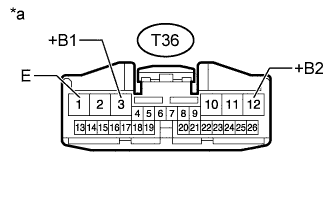
T36-1 (E) - Body ground
| Always
| Below 1 Ω
|
Measure the voltage according to the value(s) in the table below.
- Standard Voltage:
Tester Connection
| Condition
| Specified Condition
|
T36-3 (+B1) - Body ground
| Always
| 11 to 14 V
|
T36-12 (+B2) - Body ground
| Always
| 11 to 14 V
|
Text in Illustration*a
| Front view of wire harness connector
(to Theft Warning ECU Assembly)
|
| | REPAIR OR REPLACE HARNESS OR CONNECTOR |
|
|
| OK |
|
|
|
| REPLACE THEFT WARNING ECU ASSEMBLY |
|