Air Conditioning System (For Automatic Air Conditioning System) Blower Motor Circuit
DESCRIPTION
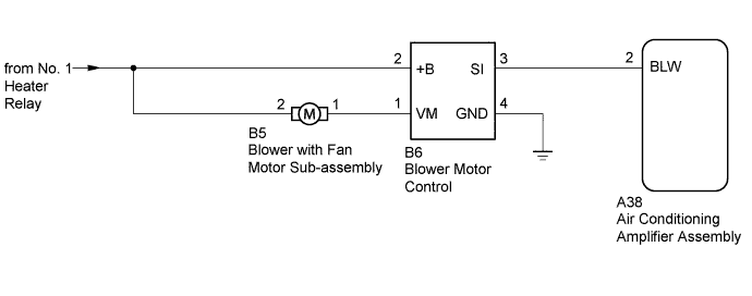
WIRING DIAGRAM
INSPECTION PROCEDURE
PERFORM ACTUATOR CHECK
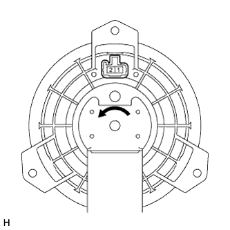
INSPECT BLOWER WITH FAN MOTOR SUB-ASSEMBLY
CHECK HARNESS AND CONNECTOR (BLOWER MOTOR CONTROL - AIR CONDITIONING AMPLIFIER AND BODY GROUND)
CHECK HARNESS AND CONNECTOR (BLOWER MOTOR CONTROL AND BLOWER WITH FAN MOTOR - BATTERY)
CHECK AIR CONDITIONING AMPLIFIER ASSEMBLY
AIR CONDITIONING SYSTEM (for Automatic Air Conditioning System) - Blower Motor Circuit |
DESCRIPTION
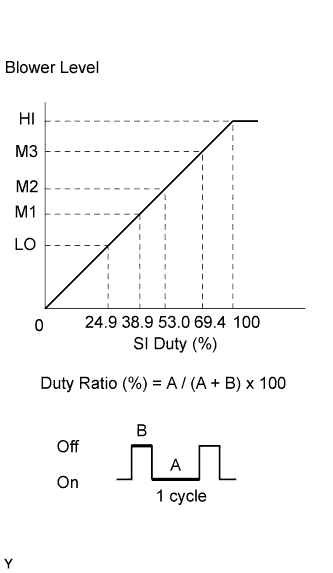 The blower with fan motor sub-assembly is operated by signals from the air conditioning amplifier. Blower with fan motor sub-assembly speed signals are determined by changes in the duty ratio*.The blower motor control controls the blower with fan motor sub-assembly speed. The blower motor control reads the signal from the air conditioning amplifier assembly and controls rotation and speed.
- HINT:
- *: The duty ratio is the ratio of the blower with fan motor sub-assembly on time (A) to the total of the blower with fan motor sub-assembly on and off time (A + B).
WIRING DIAGRAM
INSPECTION PROCEDURE
- NOTICE:
- Inspect the relays for circuits related to this system before performing the following inspection procedure.
Enter actuator check mode (Toyota Fortuner RM000003R7I00HX.html).
Place your hand in front of a vent and check that the air flow level changes according to the display code.
Display Code
| Blower Level
|
0
| 0
|
1
| 1
|
2
| 16
|
3
| 16
|
4
| 16
|
5
| 16
|
6
| 16
|
7
| 16
|
8
| 16
|
9
| 31
|
- OK:
- Blower level changes in accordance with each display code.
- HINT:
- The progression through the steps of the actuator check can be changed from automatic to manual by pressing the front DEF switch.
| 2.INSPECT BLOWER WITH FAN MOTOR SUB-ASSEMBLY |
Remove the blower with fan motor sub-assembly (Toyota Fortuner RM000004RY6008X.html).
Apply battery voltage to the blower with fan motor sub-assembly and check the operation of the blower motor.
- OK:
Measurement Condition
| Specified Condition
|
Battery positive (+) → Terminal 2
Battery negative (-) → Terminal 1
| The blower motor operates smoothly
|
| 3.CHECK HARNESS AND CONNECTOR (BLOWER MOTOR CONTROL - AIR CONDITIONING AMPLIFIER AND BODY GROUND) |
Disconnect the B6 blower motor control connector.
Disconnect the A38 air conditioning amplifier assembly connector.
Measure the resistance according to the value(s) in the table below.
- Standard Resistance:
Tester Connection
| Condition
| Specified Condition
|
B6-3 (SI) - A38-2 (BLW)
| Always
| Below 1 Ω
|
B6-4 (GND) - Body ground
|
B6-3 (SI) - Body ground
| Always
| 10 kΩ or higher
|
B6-2 (+B) - Body ground
|
B6-1 (VM) - Body ground
|
| | REPAIR OR REPLACE HARNESS OR CONNECTOR |
|
|
| 4.CHECK HARNESS AND CONNECTOR (BLOWER MOTOR CONTROL AND BLOWER WITH FAN MOTOR - BATTERY) |
Disconnect the B6 blower motor control connector.
Disconnect the B5 blower with fan motor sub-assembly connector.
Measure the voltage and resistance according to the value(s) in the table below.
- Standard Voltage:
Tester Connection
| Switch Condition
| Specified Condition
|
B6-2 (+B) - Body ground
| - Ignition switch ON
- Blower switch on (LO level)
| 11 to 14 V
|
- Ignition switch ON
- Blower switch off
| Below 1 V
|
B5-2 - Body ground
| - Ignition switch ON
- Blower switch on (LO level)
| 11 to 14 V
|
- Ignition switch ON
- Blower switch off
| Below 1 V
|
Measure the resistance according to the value(s) in the table below.
- Standard Resistance:
Tester Connection
| Condition
| Specified Condition
|
B5-1 - Body ground
| Always
| 10 kΩ or higher
|
B5-2 - Body ground
|
B6-1 (VM) - B5-1
| Always
| Below 1 Ω
|
| | REPAIR OR REPLACE HARNESS OR CONNECTOR |
|
|
| 5.CHECK AIR CONDITIONING AMPLIFIER ASSEMBLY |
Remove the air conditioning amplifier assembly with its connectors still connected (Toyota Fortuner RM000001K3A018X.html).
Using an oscilloscope, check the waveform of the amplifier.
Measurement ConditionItem
| Content
|
Tester Connection
| A38-2 (BLW) - Body ground
|
Tool Setting
| 1 V/DIV., 50 μsec./DIV.
|
Condition
| Ignition switch ON, Blower switch on (LO level)
|
- OK:
- Waveform is as shown in the illustration.
- HINT:
- Waveform varies depending on the blower switch setting.
Text in Illustration*a
| Component with harness connected
(Air Conditioning Amplifier Assembly)
|