Vehicle Stability Control System Tc And Cg Terminal Circuit
DESCRIPTION
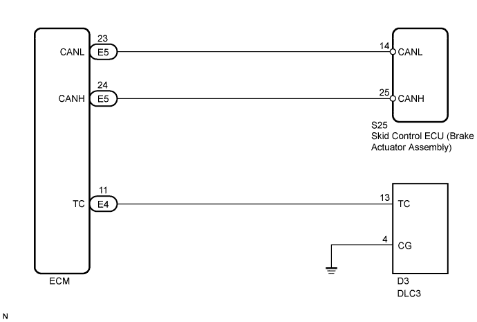
WIRING DIAGRAM
INSPECTION PROCEDURE
CHECK CAN COMMUNICATION SYSTEM
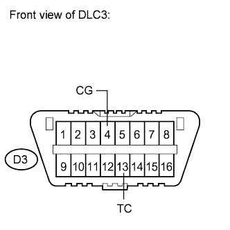
INSPECT DLC3
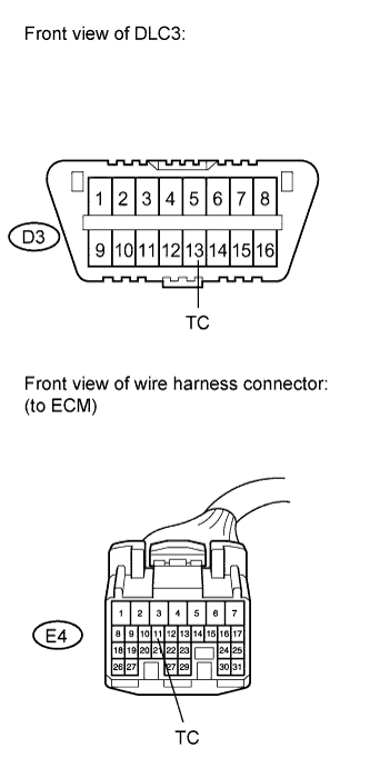
CHECK HARNESS AND CONNECTOR (DLC3 - ECM)
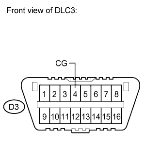
CHECK HARNESS AND CONNECTOR (CG OF DLC3 - BODY GROUND)
CHECK ECM (TC OF DLC3 INPUT)
VEHICLE STABILITY CONTROL SYSTEM - TC and CG Terminal Circuit |
DESCRIPTION
Connecting terminals TC and CG of the DLC3 causes the ECU to display the DTCs by blinking the ABS warning light.
WIRING DIAGRAM
- HINT:
- When the warning lights continue to blink, there may be a ground short in the wiring of terminal TC of the DLC3 or an internal ground short in one or more ECUs.
INSPECTION PROCEDURE
- NOTICE:
- When replacing the brake actuator assembly, perform zero point calibration (Toyota Fortuner RM000000XHR02TX.html).
| 1.CHECK CAN COMMUNICATION SYSTEM |
Check if a CAN communication system DTC is output (Toyota Fortuner RM000000XHV03YX.html).
ResultResult
| Proceed to
|
DTC is not output
| A
|
DTC is output
| B
|
| | INSPECT CAN COMMUNICATION SYSTEM |
|
|
Measure the voltage according to the value(s) in the table below.
- Standard Voltage:
Tester Connection
| Switch Condition
| Specified Condition
|
D3-13 (TC) - D3-4 (CG)
| Ignition switch ON
| 11 to 14 V
|
ResultResult
| Proceed to
|
NG
| A
|
OK
| B
|
| 3.CHECK HARNESS AND CONNECTOR (DLC3 - ECM) |
Turn the ignition switch off.
Disconnect the ECM connector.
Measure the resistance according to the value(s) in the table below.
- Standard Resistance:
Tester Connection
| Condition
| Specified Condition
|
D3-13 (TC) - E4-11 (TC)
| Always
| Below 1 Ω
|
D3-13 (TC) - Body ground
| Always
| 10 kΩ or higher
|
| | REPAIR OR REPLACE HARNESS OR CONNECTOR |
|
|
| 4.CHECK HARNESS AND CONNECTOR (CG OF DLC3 - BODY GROUND) |
Measure the resistance according to the value(s) in the table below.
- Standard Resistance:
Tester Connection
| Condition
| Specified Condition
|
D3-4 (CG) - Body ground
| Always
| Below 1 Ω
|
| | REPAIR OR REPLACE HARNESS OR CONNECTOR |
|
|
| 5.CHECK ECM (TC OF DLC3 INPUT) |
Turn the ignition switch off.
Connect the ECM connector.
Using SST, connect terminals 13 (TC) and 4 (CG) of the DLC3.
- SST
- 09843-18040
Turn the ignition switch to ON.
Check that the malfunction indicator lamp is blinking.
ResultResult
| Proceed to
|
Malfunction indicator lamp is blinking
| A
|
Malfunction indicator lamp is not blinking
| B
|
- HINT:
- If troubleshooting has been carried out according to the Problem Symptoms Table, refer back to the table and proceed to the next step before replacing the part (Toyota Fortuner RM000000XHN03SX.html).
| | REPAIR OR REPLACE WIRE HARNESS OR ECM (TC OF ECM CIRCUIT) |
|
|
| A |
|
|
|
| REPLACE BRAKE ACTUATOR ASSEMBLY |
|