Dtc C0273/13 Open In Abs Motor Relay Circuit
DESCRIPTION
WIRING DIAGRAM
INSPECTION PROCEDURE
PERFORM ACTIVE TEST USING INTELLIGENT TESTER (MOTOR RELAY)
INSPECT SKID CONTROL ECU (BM TERMINAL)
INSPECT SKID CONTROL ECU (GND TERMINAL)
RECONFIRM DTC
DTC C0273/13 Open in ABS Motor Relay Circuit |
DTC C0274/14 Short to B+ in ABS Motor Relay Circuit |
DTC C1361/91 Short Circuit in ABS Motor Fail Safe Relay Circuit |
DESCRIPTION
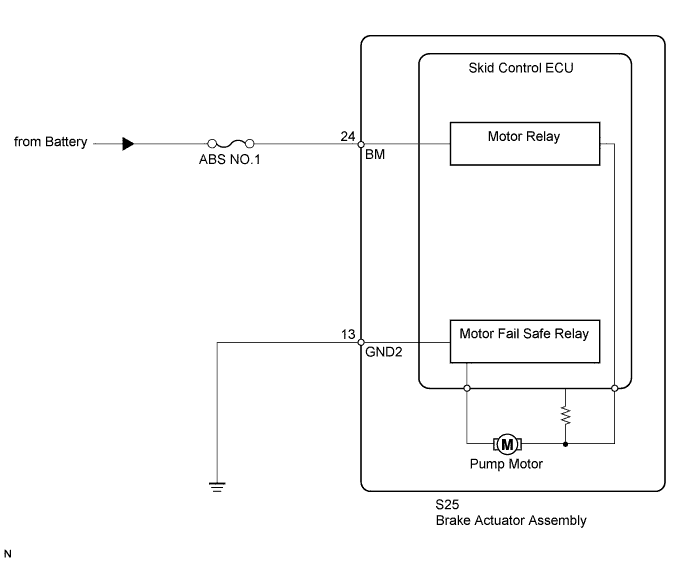
The motor relay supplies power to the pump motor. While the ABS is activated, the skid control ECU turns the motor relay on and operates the pump motor.If the voltage supplied to the motor relay (BM) is below the DTC's detection threshold due to low voltage from the battery or generator, a DTC may be stored.DTC Code
| DTC Detection Condition
| Trouble Area
|
C0273/13
| When either condition below is met:
- All of the following conditions continue for 0.1 seconds or more.
- The IG1 terminal voltage is between 9.5 and 17.2 V.
- ABS, BA, TRC or VSC is operating during initial check.
- Relay contact is open when the relay is ON.
- Both of the following conditions continue for 0.1 seconds.
- The IG1 terminal voltage is less than 9.5 V.
- Relay contact remains open when the relay is ON.
| - ABS NO. 1 fuse
- Motor relay circuit
- Brake actuator assembly (Motor relay)
|
C0274/14
| With the motor relay control signal OFF, the motor relay remains closed for 4 seconds or more.
| - Motor relay circuit
- Brake actuator assembly (Motor relay)
|
C1361/91
| Immediately after the ignition switch is turned to ON, the relay contact is closed for 4 seconds when the motor fail-safe relay is OFF.
| - ABS NO. 1 fuse
- Motor fail-safe relay circuit
- Brake actuator assembly (Motor fail-safe relay)
|
WIRING DIAGRAM
INSPECTION PROCEDURE
- NOTICE:
- When replacing the brake actuator assembly, perform zero point calibration (Toyota Fortuner RM000000XHR02TX.html).
- Inspect the fuses for circuits related to this system before performing the following inspection procedure.
- HINT:
- When C1241/41 is output together with C0273/13, C0274/13 and/or C1361/91, inspect and repair the trouble areas indicated by C1241/41 first (Toyota Fortuner RM000000XW609JX.html).
| 1.PERFORM ACTIVE TEST USING INTELLIGENT TESTER (MOTOR RELAY) |
Connect the intelligent tester to the DLC3.
Start the engine.
Select the Active Test mode on the intelligent tester (Toyota Fortuner RM000000XHW080X.html).
ABS/VSC/TRCTester Display
| Test Part
| Control Range
| Diagnostic Note
|
Motor Relay
| Motor relay
| Relay ON / OFF
| Operating sound of motor relay can be heard
|
Check for the operating sound of the motor relay when operating it with the intelligent tester.
ResultResult
| Proceed to
|
The operating sound is not heard
| A
|
The operating sound is heard
| B
|
| 2.INSPECT SKID CONTROL ECU (BM TERMINAL) |
Turn the ignition switch off.
Disconnect the skid control ECU connector.
Measure the voltage according to the value(s) in the table below.
- Standard Voltage:
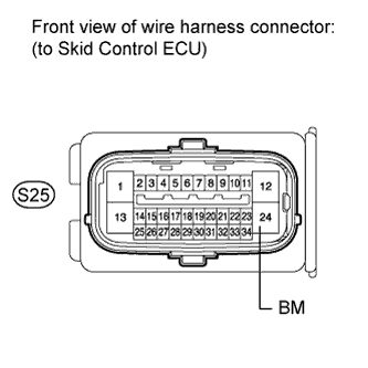
Tester Connection
| Condition
| Specified Condition
|
S25-24 (BM) - Body ground
| Always
| 11 to 14 V
|
| | REPAIR OR REPLACE HARNESS OR CONNECTOR |
|
|
| 3.INSPECT SKID CONTROL ECU (GND TERMINAL) |
Disconnect the skid control ECU connector.
Measure the resistance according to the value(s) in the table below.
- Standard Resistance:
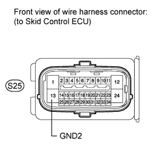
Tester Connection
| Condition
| Specified Condition
|
S25-13 (GND2) - Body ground
| Always
| Below 1 Ω
|
| | REPAIR OR REPLACE HARNESS OR CONNECTOR |
|
|
- HINT:
- These codes are detected when a problem is identified in the brake actuator assembly.
- The motor relay is in the brake actuator assembly.
- Therefore, motor relay circuit inspection and motor relay unit inspection cannot be performed. Be sure to check if a DTC is output before replacing the brake actuator assembly.
Turn the ignition switch off.
Reconnect the skid control ECU connector.
Clear the DTC(s) (Toyota Fortuner RM000000XHV09NX.html).
Start the engine.
Drive the vehicle at a speed of 40 km/h (25 mph) or more for 30 seconds or more.
Check if the same DTC is recorded (Toyota Fortuner RM000000XHV09NX.html).
ResultResult
| Proceed to
|
DTC not output
| A
|
DTC output
| B
|
- HINT:
- If a speed signal of 6 km/h (4 mph) or more is input to the skid control ECU with the ignition switch ON and the stop light switch off, the ECU performs self diagnosis of the motor and solenoid circuits.
- If the normal system code is output (a trouble code is not output), slightly jiggle the connectors, wire harnesses, and fuses of the brake actuator assembly. Make sure that no DTCs are output.
- If any DTCs are output while jiggling a connector or wire harness of the skid control ECU (brake actuator assembly), inspect and repair the connector or wire harness.
- The DTCs may be output due to a bad connection at the connector terminal.
| | REPLACE BRAKE ACTUATOR ASSEMBLY |
|
|
| A |
|
|
|
| USE SIMULATION METHOD TO CHECK |
|