Dtc C1246/46 Master Cylinder Pressure Sensor Malfunction
DESCRIPTION
WIRING DIAGRAM
INSPECTION PROCEDURE
CHECK STOP LIGHT OPERATION
READ VALUE USING INTELLIGENT TESTER (MASTER CYLINDER SENSOR)
READ VALUE USING INTELLIGENT TESTER (STOP LIGHT SW)
RECONFIRM DTC
INSPECT SKID CONTROL ECU (STP TERMINAL)
DTC C1246/46 Master Cylinder Pressure Sensor Malfunction |
DTC C1281/81 Master Cylinder Pressure Sensor Output Malfunction (Test Mode DTC) |
DESCRIPTION
The master cylinder pressure sensor is connected to the skid control ECU in the brake actuator assembly.DTC C1281/81 is deleted when the master cylinder pressure sensor sends a master cylinder pressure signal or Test Mode ends. DTC C1281/81 is output only in Test Mode.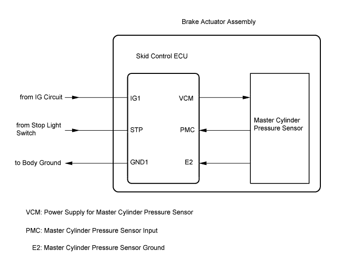
DTC Code
| DTC Detection Condition
| Trouble Area
|
C1246/46
| When one of the following conditions is met:
- At a vehicle speed of 7 km/h (4.3 mph) or more, the PMC terminal voltage is over 0.86 V and does not change by 0.005 V or more for 30 seconds.
- Noise occurs in the PMC terminal 7 times or more within 5 seconds.
- With the stop light switch OFF, the PMC terminal voltage is more than 0.86 V or less than 0.3 V for 5 seconds or more.
- With the IG1 terminal voltage between 9.5 and 17.2 V, the VCM terminal voltage is not between 4.4 and 5.6 V for 1.2 seconds or more.
- With the VCM terminal voltage between 4.4 and 5.6 V, the PCM terminal voltage is not between 0.14 and 4.85 V for 1.2 seconds or more.
| - Stop light switch circuit
- Master cylinder pressure sensor circuit
- Brake actuator assembly (Master cylinder pressure sensor)
|
C1281/81
| Detected only during Test Mode.
| - Stop light switch
- Master cylinder pressure sensor
|
WIRING DIAGRAM
Refer to DTC C1249/49 (Toyota Fortuner RM000000XIE04EX_02.html).
INSPECTION PROCEDURE
- NOTICE:
- When replacing the brake actuator assembly, perform zero point calibration (Toyota Fortuner RM000000XHR02TX.html).
| 1.CHECK STOP LIGHT OPERATION |
Check that the stop light comes on when the brake pedal is depressed, and goes off when the brake pedal is released.
- OK:
Condition
| Illumination Condition
|
Brake pedal depressed
| ON
|
Brake pedal released
| OFF
|
| | INSPECT STOP LIGHT CIRCUIT |
|
|
| 2.READ VALUE USING INTELLIGENT TESTER (MASTER CYLINDER SENSOR) |
Connect the intelligent tester to the DLC3.
Start the engine.
Select the Data List mode on the intelligent tester (Toyota Fortuner RM000000XHW03RX.html).
ABS/VSC/TRCTester Display
| Measurement Item/Range
| Normal Condition
| Diagnostic Note
|
Master Cylinder Sensor
| Master cylinder pressure sensor reading / min.: 0 V, max.: 5 V
| When brake pedal is released: 0.3 to 0.9 V
| Reading increases when brake pedal is depressed
|
Check that the value of the master cylinder pressure sensor observed on the intelligent tester changes when the brake pedal is depressed.
- OK:
- When the pedal is depressed, the voltage displayed on the intelligent tester increases.
| | REPLACE BRAKE ACTUATOR ASSEMBLY |
|
|
| 3.READ VALUE USING INTELLIGENT TESTER (STOP LIGHT SW) |
Select the Data List mode on the intelligent tester (Toyota Fortuner RM000000XHW03RX.html).
ABS/VSC/TRCTester Display
| Measurement Item/Range
| Normal Condition
| Diagnostic Note
|
Stop Light SW
| Stop light switch / ON or OFF
| ON: Brake pedal depressed
OFF: Brake pedal released
| -
|
Check that the stop light switch condition observed on the intelligent tester changes when the brake pedal is depressed.
- OK:
- When the brake pedal is depressed, the intelligent tester displays "ON".
Turn the ignition switch off.
Clear the DTC(s) (Toyota Fortuner RM000000XHV03YX.html).
Start the engine.
Drive the vehicle at a vehicle speed of 30 km/h (19 mph) and depress the brake pedal strongly for approximately 3 seconds to perform a braking test (decelerate the vehicle by depressing the brake pedal).
Check if the same DTC is recorded (Toyota Fortuner RM000000XHV03YX.html).
ResultResult
| Proceed to
|
DTC not output
| A
|
DTC output
| B
|
| | REPLACE BRAKE ACTUATOR ASSEMBLY |
|
|
| A |
|
|
|
| CHECK FOR INTERMITTENT PROBLEMS |
|
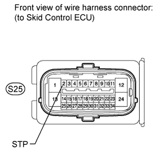
| 5.INSPECT SKID CONTROL ECU (STP TERMINAL) |
Turn the ignition switch off.
Disconnect the skid control ECU connector.
Measure the voltage according to the value(s) in the table below.
- Standard Voltage:
Tester Connection
| Switch Condition
| Specified Condition
|
S25-2 (STP) - Body ground
| Stop light switch ON
(Brake pedal depressed)
| 8 to 14 V
|
S25-2 (STP) - Body ground
| Stop light switch OFF
(Brake pedal released)
| Below 1.5 V
|
| | REPAIR OR REPLACE HARNESS OR CONNECTOR (STP CIRCUIT) |
|
|
| OK |
|
|
|
| REPLACE BRAKE ACTUATOR ASSEMBLY |
|