Generator -- Inspection |
| 1. INSPECT GENERATOR ROTOR ASSEMBLY |
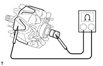
Check the rotor for an open circuit.
Measure the resistance between the slip rings.
- Standard resistance:
- 1.8 to 2.8 Ωat 20°C (68°F)
 |
Check if the rotor is grounded.
Measure the resistance between the slip ring and rotor.
- Standard resistance:
- 10 kΩ or higher
 |
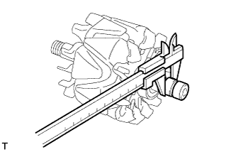
Check that the slip rings are not rough or scored.
If rough or scored, replace the rotor assembly.
Using a vernier caliper, measure the slip ring diameter.
- Standard diameter:
- 15.3 to 15.5 mm (0.602 to 0.610 in.)
- Minimum diameter:
- 14.9 mm (0.587 in.)
 |
| 2. INSPECT GENERATOR STATOR SUB-ASSEMBLY WITH RECTIFIER |

- HINT:
- For terminal positions of the stator generator, refer to the illustration.
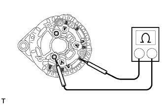
Inspect the positive (+) rectifier.
- HINT:
- Inspect the positive terminal after pulling it up.
Using an ohmmeter, connect one tester probe to the positive (+) terminal and the other to each rectifier terminal.
Reverse the polarity of the tester probes and repeat the step above.
Check that one shows a resistance of below 1 Ω and the other shows a resistance of 10 kΩ or higher.
If the result is not as specified, replace the generator stator sub-assembly with rectifier.
 |
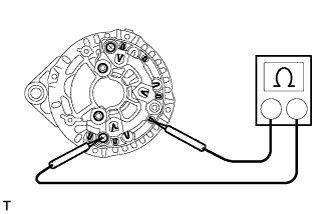
Inspect the negative (-) rectifier.
Using an ohmmeter, connect one tester probe to the negative (-) terminal and the other to each rectifier terminal.
Reverse the polarity of the tester probes and repeat the step above.
Check that one shows a resistance of below 1 Ω and the other shows a resistance of 10 kΩ or higher.
If the result is not as specified, replace the generator stator sub-assembly with rectifier.
 |
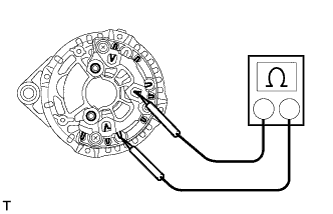
Inspect the stator coil for an open circuit.
Measure the resistance between the rectifier terminals.
- Standard resistance:
- Below 1 Ω
 |
| 3. INSPECT BRUSH |
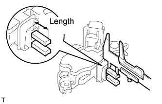 |
Using a vernier caliper, measure the exposed brush length.
- Standard exposed length on new brush:
- 13.2 mm (0.520 in.)
- Minimum exposed length:
- 6.0 mm (0.236 in.)
| 4. INSPECT GENERATOR PULLEY WITH CLUTCH |
When rotating the outer part of the pulley, check that it is as follows: 1) rotating it clockwise causes the inner and outer part of the pulley to turn together; and 2) rotating it counterclockwise causes only the outer part of the pulley to turn.
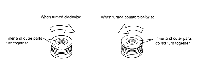
If the result is not as specified, replace the generator pulley with clutch.