Intake System System Diagram
INTAKE AIR CONTROL SYSTEM ILLUSTRATION
INTAKE AIR CONTROL SYSTEM WIRING DIAGRAM
TURBOCHARGER SYSTEM ILLUSTRATION
TURBOCHARGER SYSTEM WIRING DIAGRAM
Intake System -- System Diagram |
| INTAKE AIR CONTROL SYSTEM ILLUSTRATION |
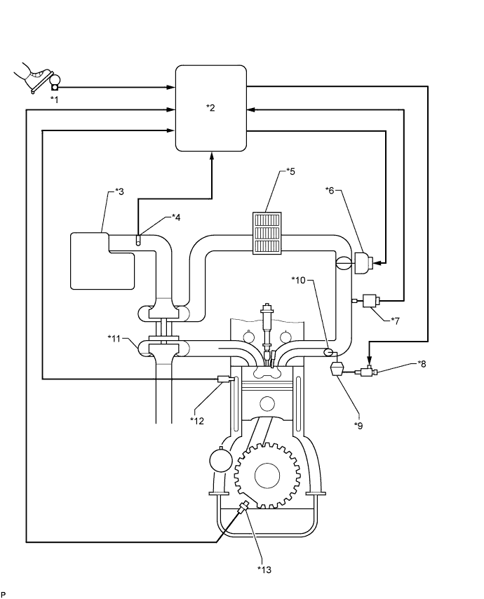
The swirl control valve is mounted on the intake manifold. The Vacuum Switching Valve (VSV) for swirl control valve changes the vacuum to actuate the actuator.First, the ECM determines the opening angle of the swirl control valve. Then it uses the swirl control valve VSV to change the vacuum applied to the actuator's diaphragm to open and close the swirl control valve.Text in Illustration*1
| Accelerator Pedal Sensor
| *2
| ECM
|
*3
| Air Cleaner
| *4
| Mass Air Flow Meter
|
*5
| Intercooler
| *6
| Diesel Throttle Body
|
*7
| Manifold Absolute Pressure Sensor
| *8
| Vacuum Switching Valve (for Swirl Control Valve)
|
*9
| Swirl Control Valve Actuator
| *10
| Swirl Control Valve
|
*11
| Turbocharger
| *12
| Engine Coolant Temperature Sensor
|
*13
| Crankshaft Position Sensor
| -
| -
|
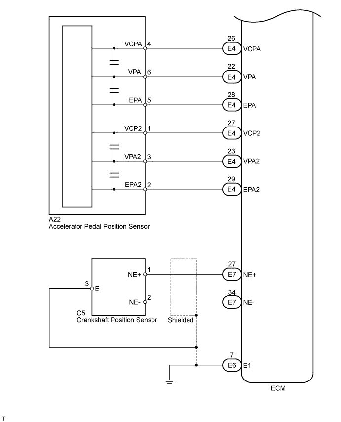
| INTAKE AIR CONTROL SYSTEM WIRING DIAGRAM |
| TURBOCHARGER SYSTEM ILLUSTRATION |
- The turbocharger system is comprised of the Variable Nozzle (VN) type turbocharger, turbo motor driver and ECM.
- The turbocharger has a nozzle vane which opens and closes to control the volume of the exhaust gas flowing into the turbine. This, in turn, controls the boost pressure. When the nozzle vane moves towards the closing direction, the pressure increases. When the vane moves towards the opening direction, the pressure decreases.
- The turbocharger actuator built on the compressor housing side activates the nozzle vane. The nozzle vane position sensor built on the actuator detects the opening angle of the nozzle vane. The turbo motor driver receives an opening angle request from the ECM and a nozzle vane position sensor signal. Based on these signals, the turbo motor driver operates the DC motor and controls the turbocharger's opening angle. The turbo motor driver sends the status as a turbo driver status signal to the ECM.
- The ECM sends a target nozzle vane position signal to the turbo motor driver to obtain the nozzle vane position for optimal pressure in accordance with the driving conditions.
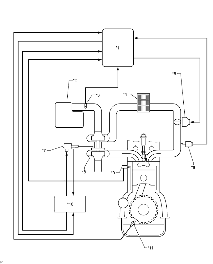
Text in Illustration*1
| ECM
| *2
| Air Cleaner
|
*3
| Mass Air Flow Meter
| *4
| Intercooler
|
*5
| Diesel Throttle Body
| *6
| Manifold Absolute Pressure Sensor
|
*7
| Actuator
- DC Motor
- Nozzle Vane Position Sensor
| *8
| Turbocharger
|
*9
| Engine Coolant Temperature Sensor
| *10
| Turbo Motor Driver
|
*11
| Crankshaft Position Sensor
| -
| -
|
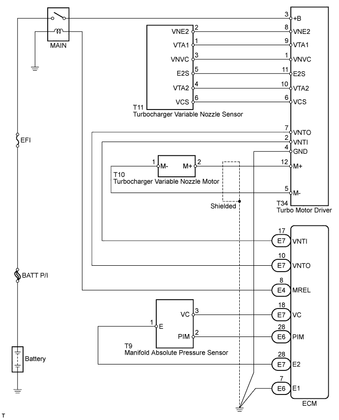
| TURBOCHARGER SYSTEM WIRING DIAGRAM |