Fuel Injection Nozzle -- Installation |
| 1. INSTALL NOZZLE HOLDER AND NOZZLE SET |
Place 4 new injection nozzle seat gaskets and 4 injection nozzle seats into the injection nozzle holes of the cylinder head.
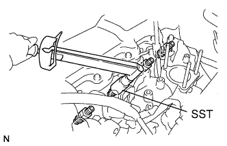 |
Using SST, install the 4 nozzle holders and nozzle sets.
- SST
- 09268-64010(09268-64020)
- Torque:
- 64 N*m{650 kgf*cm, 47 ft.*lbf}
| 2. INSTALL NOZZLE LEAKAGE PIPE ASSEMBLY |
Install 4 new ring packing washers and the leakage pipe with the 4 nuts.
- Torque:
- 29.5 N*m{300 kgf*cm, 22 ft.*lbf}
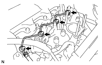 |
Connect the fuel hose to the leakage pipe.
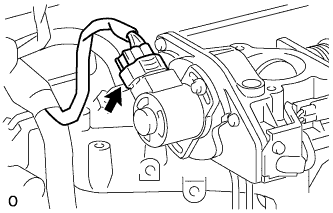
| 3. INSTALL NO. 1 GLOW PLUG CONNECTOR |
Install the glow plug connector by uniformly tightening the 4 nuts.
- Torque:
- 1.0 N*m{10 kgf*cm, 9 in.*lbf}
Install the 4 screw grommets.
Connect the glow plug connector wire with the nut.
- Torque:
- 8.4 N*m{85 kgf*cm, 74 in.*lbf}
| 4. INSTALL INJECTION PIPE SET |
Connect the 2 lower pipe clamps onto the intake manifold.
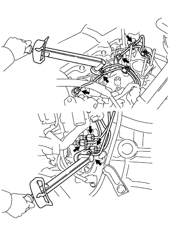 |
Install the 4 injection pipes.
- Torque:
- 25 N*m{250 kgf*cm, 18 ft.*lbf}
- NOTICE:
- Use the formula to calculate special torque values for situations where a union nut wrench is combined with a torque wrench (Toyota Fortuner RM000000UYX010X.html).
Secure the injection pipes with the 2 upper pipe clamps and 2 nuts.
- Torque:
- 5.0 N*m{51 kgf*cm, 44 in.*lbf}
| 5. BLEED INJECTION PIPE |
Move the priming pump in the upper part of the fuel filter assembly up and down, and fill the injection pump assembly and fuel system with fuel.
Loosen one of the union nuts (on the nozzle side).
Crank the engine until fuel comes out from the union nut (on the nozzle side).
Tighten the union nut.
- Torque:
- 25 N*m{250 kgf*cm, 18 ft.*lbf}
- NOTICE:
- Use the formula to calculate special torque values for situations where a union nut wrench is combined with a torque wrench (Toyota Fortuner RM000000UYX010X.html).
Perform the procedures above for each injection pipe.
| 6. INSTALL VENTURI |
Place a new gasket and the venturi on the intake manifold.
Connect the throttle control motor connector.
 |
Connect the throttle open switch connector.
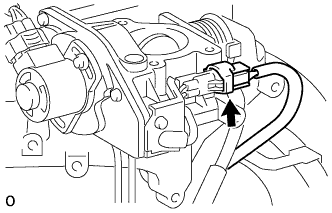 |
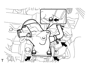
| 7. INSTALL INTAKE FLANGE |
Install a new gasket and the intake flange with the 3 nuts.
- Torque:
- 12 N*m{122 kgf*cm, 9 ft.*lbf}
 |
Connect the ventilation hose with the clamp.
Connect the manifold absolute pressure sensor connector.
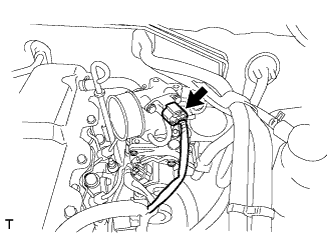 |
Install the clamp of the heater hose with the bolt.
- Torque:
- 5.0 N*m{51 kgf*cm, 44 in.*lbf}
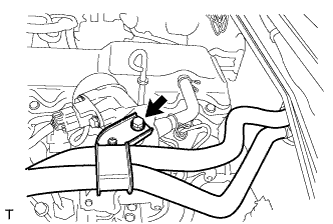 |
| 8. INSTALL INTAKE PIPE ASSEMBLY |
Connect the intake pipe to the intake flange with the clamp.
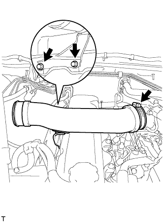 |
Fix the intake pipe in place with the 2 bolts and clamp.
- Torque:
- 18 N*m{184 kgf*cm, 13 ft.*lbf}for bolt
- 6.0 N*m{61 kgf*cm, 53 in.*lbf}for clamp
| 9. CONNECT AIR CLEANER HOSE |
Connect the air cleaner hose to the air cleaner and intake pipe with the 2 clamps.
Fix the intake pipe in place with the 2 clamps.
- Torque:
- 5.0 N*m{51 kgf*cm, 44 in.*lbf}
Connect the intake air temperature sensor connector.
Attach the clamp of the intake air temperature sensor harness.
| 10. CONNECT CABLE TO NEGATIVE BATTERY TERMINAL |
| 11. INSPECT FOR FUEL LEAK |
Check that there are no fuel leaks anywhere on the fuel system after performing maintenance.
- HINT:
- When checking for fuel leaks, make sure that there is pressure in the fuel line.