Engine Unit -- Disassembly |
| 1. REMOVE CYLINDER HEAD |
Remove the cylinder head (Toyota Fortuner RM00000128G003X.html).
| 2. REMOVE NO. 1 TIMING BELT IDLER SUB-ASSEMBLY |
Remove the 2 bolts (A and B).
 |
Loosen the bolt (C), and remove the No. 1 timing belt idler.
| 3. REMOVE NO. 2 TIMING BELT IDLER SUB-ASSEMBLY |
Remove the bolt, No. 2 timing belt idler and spacer.
| 4. REMOVE WATER PUMP ASSEMBLY |
Remove the 6 bolts and tension spring bracket.
 |
Remove the water pump and gasket.
| 5. REMOVE CRANKSHAFT TIMING PULLEY |
Using SST, remove the timing pulley.
- SST
- 09950-50013(09951-05010,09952-05010,09953-05010,09953-05020,09954-05010)
 |
| 6. REMOVE OIL PAN SUB-ASSEMBLY |
Remove the 16 bolts and 2 nuts.
Insert the blade of SST between the oil pan and cylinder block, cut off the applied sealer and remove the oil pan.
- SST
- 09032-00100
- NOTICE:
- Do not use SST for the timing belt case side and rear oil seal retainer.
- Be careful not to damage the oil pan flange.
 |
| 7. REMOVE OIL STRAINER SUB-ASSEMBLY |
Remove the 2 bolts, 2 nuts, oil strainer and gasket.
| 8. REMOVE TIMING BELT CASE SUB-ASSEMBLY |
Remove the 5 bolts, timing belt case and gasket.
 |
| 9. REMOVE ENGINE REAR OIL SEAL RETAINER |
Remove the 4 bolts, oil seal retainer and gasket.
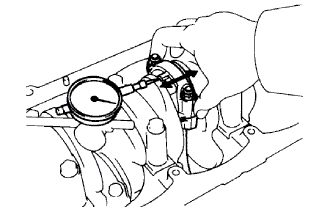
| 10. INSPECT CONNECTING ROD THRUST CLEARANCE |
Using a dial indicator, measure the thrust clearance while moving the connecting rod back and forth.
- Standard thrust clearance:
- 0.080 to 0.300 mm (0.0031 to 0.0118 in.)
- Maximum thrust clearance:
- 0.35 mm (0.0138 in.)
 |
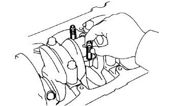
| 11. INSPECT CONNECTING ROD OIL CLEARANCE |
Check the matchmarks on the connecting rod and cap to ensure correct reassembly.
 |
Remove the 2 connecting rod cap nuts.
Using a plastic-faced hammer, lightly tap the connecting rod bolts and lift off the connecting rod cap.
- HINT:
- Keep the lower bearing inserted with the connecting rod cap.
 |
Clean the crank pin and bearing.
Check the crank pin and bearing for pitting and scratches.
If the crank pin or bearing is damaged, replace the bearings. If necessary, grind or replace the crankshaft.
Lay a strip of Plastigage across the crank pin.
 |
Place the connecting rod cap on the connecting rod.
Match the numbered connecting rod cap with the connecting rod.
Install the connecting rod cap with the front mark facing forward.

Install the connecting rod cap with the 2 nuts.
If any connecting rod bolt is broken or deformed, replace it.- HINT:
- The connecting rod cap nuts are tightened in 2 progressive steps.
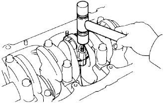
Apply a light of engine oil to the threads and under the heads of the connecting rod cap nuts.
Install and alternately tighten the nuts of the connecting rod cap in several passes.
- Torque:
- 54 N*m{551 kgf*cm, 40 ft.*lbf}
- NOTICE:
- Do not turn the crankshaft.
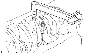
Mark the front of the connecting rod cap nuts with paint.
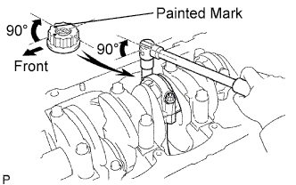
Retighten the connecting rod cap nuts 90° as shown.
Check that the painted marks is now at a 90° angle to the front.
Remove the 2 nuts, connecting rod cap and lower bearing.
Measure the Plastigage at its widest point.
- Standard oil clearance:
Item Specified Condition STD 0.036 to 0.064 mm (0.0014 to 0.0025 in.) U/S 0.25, U/S 0.50 0.033 to 0.079 mm (0.0013 to 0.0031 in.)
- Maximum oil clearance:
- 0.10 mm (0.0039 in.)
 |
If using a standard bearing, replace it with one having the same number marked on the connecting rod cap. There are 3 sizes of standard bearings, marked 1, 2 and 3 accordingly.
- Standard sized bearing center wall thickness:
Mark Specified Condition 1 1.478 to 1.482 mm (0.0582 to 0.0583 in.) 2 1.482 to 1.486 mm (0.0583 to 0.0585 in.) 3 1.486 to 1.490 mm (0.0585 to 0.0587 in.)
Completely remove the Plastigage.
 |
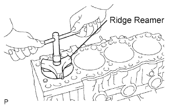
| 12. REMOVE PISTON AND CONNECTING ROD |
Using a ridge reamer, remove all the carbon from the top of the cylinder.
 |
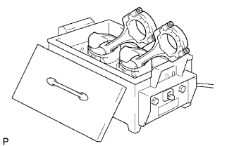
Cover the connecting rod bolts with a short piece of hose to protect the crankshaft from damage.
 |
Push the piston, connecting rod assembly and upper bearing through the top of the cylinder block.
- HINT:
- Keep the bearings, connecting rod and cap together.
- Arrange the piston and connecting rod assemblies in the correct order.
| 13. REMOVE PISTON SUB-ASSEMBLY |
Check the fitting condition between the piston and piston pin.
Try to move the piston back and forth on the piston pin.
If any movement is felt, replace the piston and pin a set.

Using a piston ring expander, remove the 2 compression rings.
- HINT:
- Be sure to organize the removed piston rings so that they can reinstalled exactly as before.
 |
Remove the oil ring and coil by hand.
- HINT:
- Arrange the piston rings in the correct order.
Disconnect the connecting rod from the piston.
Using snap ring pliers, remove the 2 snap rings from the piston.
Gradually heat the piston to approximately. 60°C (140°F).
Using a plastic-faced hammer and brass bar, lightly tap out the piston pin and pin and remove the connecting rod.
- HINT:
- The piston and pin are a matched set.
- Arrange the pistons, pins, rings, connecting rods and bearings in the correct order.


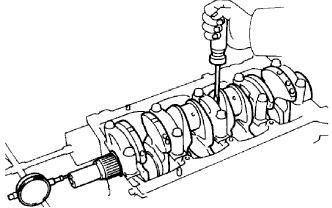
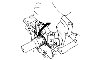
| 14. INSPECT CRANKSHAFT THRUST CLEARANCE |
Using a dial indicator, measure the thrust clearance while prying the crankshaft back and forth with a screwdriver.
- Standard thrust clearance:
- 0.040 to 0.250 mm (0.0016 to 0.0098 in.)
- Maximum thrust clearance:
- 0.30 mm (0.0118 in.)
- Thrust washer thickness:
Item Specified Condition STD 2.430 to 2.480 mm (0.0957 to 0.0976 in.) O/S 0.125 2.493 to 2.543 mm (0.0981 to 0.1001 in.) O/S 0.250 2.555 to 2.605 mm (0.1006 to 0.1026 in.)
 |
| 15. REMOVE CRANKSHAFT AND INSPECT OIL CLEARANCE |
Uniformly loosen and remove the 10 crankshaft bearing cap bolts in several passes, in the sequence shown in the illustration.
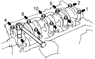 |
Using the removed crankshaft bearing cap bolts, pry the cap back and forth, and remove the crankshaft bearing caps, lower bearings and lower thrust washers.
- HINT:
- Only the No. 3 crankshaft bearing cap has lower thrust washers.
- Keep the lower bearing and crankshaft bearing caps together.
- Be sure to organize the bearing caps and lower thrust washers so that they can be reinstalled exactly as before.
 |
Clean each crankshaft journal and bearing.
Check each crankshaft journal and bearing for pitting and scratches.
If the journal or bearing is damaged, replace the bearings. If necessary, grind or replace the crankshaft.
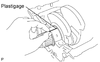
Place the crankshaft on the cylinder block.
Lay a strip of Plastigage across each journal.
 |
Install the 5 crankshaft bearing caps in their proper locations.
- NOTICE:
- Do not turn the crankshaft.
 |
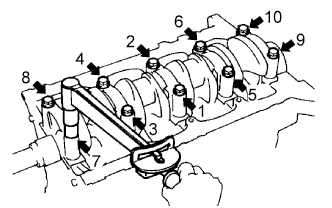
Install the crankshaft bearing cap bolts.
Apply a light coat of the engine oil to the threads and under the bolt heads of the crankshaft bearing caps.
Install and uniformly tighten the 10 bolts of the crankshaft bearing caps, in several steps, in the sequence shown in the illustration.
- Torque:
- 105 N*m{1,071 kgf*cm, 77 ft.*lbf}
Remove the 10 bolts and 5 crankshaft bearing caps.
Measure the Plastigage at its widest point.
- Standard oil clearance:
Item Specified Condition STD 0.034 to 0.065 mm (0.0013 to 0.0026 in.) U/S 0.25, U/S 0.50 0.033 to 0.079 mm (0.0013 to 0.0031 in.)
- Maximum oil clearance:
- 0.10 mm (0.0039 in.)
 |
If using a standard bearing, replace it with one having the same number marked on the connecting rod cap. There are 3 sizes of standard bearings, marked 1, 2 and 3 accordingly.
- Standard sized bearing center wall thickness:
Mark Specified Condition 1 1.979 to 1.983 mm (0.0779 to 0.0781 in.) 2 1.983 to 1.987 mm (0.0781 to 0.0782 in.) 3 1.987 to 1.991 mm (0.0782 to 0.0784 in.)
 |
Completely remove the Plastigage.
Lift out the crankshaft.
- HINT:
- Keep the upper crankshaft bearings and upper thrust washers together with the cylinder block.
| 16. REMOVE NO. 1 OIL NOZZLE SUB-ASSEMBLY |
Remove the 4 check valves and oil nozzles.
| 17. REMOVE CYLINDER BLOCK OIL ORIFICE |
Using a 6 mm hexagon wrench, remove the oil orifice.
| 18. REMOVE CYLINDER BLOCK WATER DRAIN COCK SUB-ASSEMBLY |
Remove the water drain cock from the cylinder block.