Valve Clearance -- Adjustment |
- NOTICE:
- When replacing the injectors (including shuffling the injectors between the cylinders), common rail or cylinder head, it is necessary to replace the injection pipes with new ones.
- When replacing the fuel supply pump, common rail, cylinder block, cylinder head, cylinder head gasket or timing gear case, it is necessary to replace the fuel inlet pipe with a new one.
- After removing the injection pipes, clean them with a brush and compressed air.
- HINT:
- The injectors do not need to be removed when inspecting the valve clearance.
| 1. REMOVE CYLINDER HEAD COVER SUB-ASSEMBLY |
| 2. SET NO. 1 CYLINDER TO TDC/COMPRESSION |
Align the matchmarks of the crankshaft pulley and timing gear case cover by rotating the crankshaft clockwise.
- HINT:
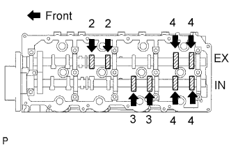
- Make sure that both cam-noses (intake side and exhaust side) of the No. 1 cylinder face upward.
 |
| 3. INSPECT VALVE CLEARANCE |
Check only the valves indicated.
Using a feeler gauge, measure the clearance between the valve lifter and camshaft.
- Standard valve clearance (Cold):
Intake Exhaust 0.20 to 0.30 mm (0.008 to 0.012 in.) 0.35 to 0.45 mm (0.014 to 0.018 in.)
 |
Turn the crankshaft 360° to set the No. 4 cylinder to TDC / compression.
Check only the valves indicated.
Using a feeler gauge, measure the clearance between the valve lifter and camshaft.
- Standard valve clearance:
Intake Exhaust 0.20 to 0.30 mm (0.008 to 0.012 in.) 0.35 to 0.45 mm (0.014 to 0.018 in.)
 |
| 4. ADJUST VALVE CLEARANCE |
Remove the fuel injector.
Remove the timing belt.
Remove the camshaft timing pulley.
Remove the No. 2 timing belt cover.
Remove the camshafts.
Remove the valve lifters.
Determine the replacement valve lifter size by following the procedures below.
Using a micrometer, measure the thickness of the removed lifter.
Calculate the thickness of a new lifter so that the valve clearance comes within the specified value.
A B C New lifter thickness Used lifter thickness Measured valve clearance - New lifter thickness:
- Intake A = B + (C - 0.25 mm (0.0098 in.))
- Exhaust A = B + (C - 0.40 mm (0.00158 in.))
Select a new lifter with a thickness as close as possible to the calculated values.
- HINT:
- Valve lifters are available in 35 sizes in increments of 0.020 mm (0.0008 in.), from 5.060 mm (0.1992 in.) to 5.740 mm (0.2260 in.).
Valve lifter selection chart (intake).

Valve lifter selection chart (intake) (continued).
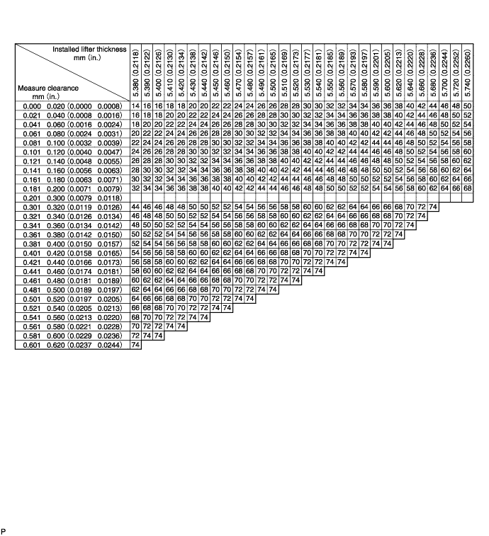
- Standard intake valve clearance (Cold):
- 0.20 to 0.30 mm (0.008 to 0.012 in.)
- EXAMPLE:
- The 5.250 mm (0.2067 in.) lifter is installed, and the measured clearance is 0.400 mm (0.0158 in.). Replace the 5.250 mm (0.2067 in.) shim with a No. 40 lifter.
- New lifter thickness (mm (in.)):
Shim No. Thickness Shim No. Thickness Shim No. Thickness 06 5.060 (0.1992) 30 5.300 (0.2087) 54 5.540 (0.2181) 08 5.080 (0.2000) 32 5.320 (0.2094) 56 5.560 (0.2189) 10 5.100 (0.2008) 34 5.340 (0.2102) 58 5.580 (0.2197) 12 5.120 (0.2016) 36 5.360 (0.2110) 60 5.600 (0.2205) 14 5.140 (0.2024) 38 5.380 (0.2118) 62 5.620 (0.2213) 16 5.160 (0.2031) 40 5.400 (0.2126) 64 5.640 (0.2220) 18 5.180 (0.2039) 42 5.420 (0.2134) 66 5.660 (0.2228) 20 5.200 (0.2047) 44 5.440 (0.2142) 68 5.680 (0.2236) 22 5.220 (0.2055) 46 5.460 (0.2150) 70 5.700 (0.2244) 24 5.240 (0.2063) 48 5.480 (0.2157) 72 5.720 (0.2252) 26 5.260 (0.2071) 50 5.500 (0.2165) 74 5.740 (0.2260) 28 5.280 (0.2079) 52 5.520 (0.2173) - -
Valve lifter selection chart (exhaust).

Valve lifter selection chart (exhaust) (continued).
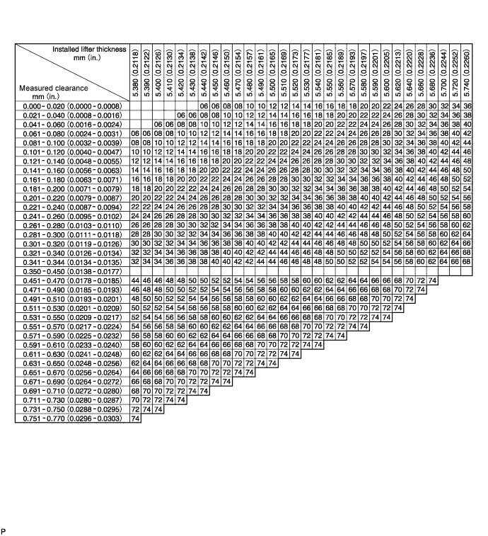
- Standard exhaust valve clearance (Cold):
- 0.35 to 0.45 mm (0.014 to 0.018 in.)
- EXAMPLE:
- The 5.340 mm (0.2102 in.) lifter is installed, and the measured clearance is 0.480 mm (0.0189 in.). Replace the 5.340 mm (0.2102 in.) shim with a No. 42 lifter.
- New lifter thickness (mm (in.)):
Shim No. Thickness Shim No. Thickness Shim No. Thickness 06 5.060 (0.1992) 30 5.300 (0.2087) 54 5.540 (0.2181) 08 5.080 (0.2000) 32 5.320 (0.2094) 56 5.560 (0.2189) 10 5.100 (0.2008) 34 5.340 (0.2102) 58 5.580 (0.2197) 12 5.120 (0.2016) 36 5.360 (0.2110) 60 5.600 (0.2205) 14 5.140 (0.2024) 38 5.380 (0.2118) 62 5.620 (0.2213) 16 5.160 (0.2031) 40 5.400 (0.2126) 64 5.640 (0.2220) 18 5.180 (0.2039) 42 5.420 (0.2134) 66 5.660 (0.2228) 20 5.200 (0.2047) 44 5.440 (0.2142) 68 5.680 (0.2236) 22 5.220 (0.2055) 46 5.460 (0.2150) 70 5.700 (0.2244) 24 5.240 (0.2063) 48 5.480 (0.2157) 72 5.720 (0.2252) 26 5.260 (0.2071) 50 5.500 (0.2165) 74 5.740 (0.2260) 28 5.280 (0.2079) 52 5.520 (0.2173) - -

Install the selected valve lifter.
Install the camshaft.
Install the No. 2 timing belt cover.
Install the camshaft timing pulley.
Install the timing belt.
Install the fuel injector.
| 5. INSTALL CYLINDER HEAD COVER SUB-ASSEMBLY |
| 6. BLEED AIR FROM FUEL SYSTEM |
 |
Using the hand pump, bleed air from the fuel system until pumping becomes difficult.
| 7. INSPECT FOR FUEL LEAK |
- CAUTION:
- During Active Test mode, engine speed becomes high and combustion noise becomes loud, so pay attention.
- During Active Test mode, fuel becomes high-pressured. Be extremely careful not to expose your eyes, hands, or body to escaped fuel.
Check that there are no leaks from any part of the fuel system when the engine is stopped. If there is fuel leakage, repair or replace parts as necessary.
Start the engine and check that there are no leaks from any part of the fuel system. If there is fuel leakage, repair or replace parts as necessary.
Disconnect the return hose from the common rail.
Start the engine and check for fuel leaks from the return pipe.
If there is fuel leakage, replace the common rail.
Connect the intelligent tester to the DLC3.
Start the engine and push the intelligent tester main switch on.
Select the Fuel Leak test from the Active Test mode on the intelligent tester.
If the intelligent tester is not available, fully depress the accelerator pedal quickly. Increase the engine speed to the maximum and maintain that speed for 2 seconds. Repeat this operation several times.
Check that there are no leaks from any part of the fuel system.
- NOTICE:
- A return pipe leakage of less than 10 cc (0.6 cu in.) per minute is acceptable.
Reconnect the return hose to the common rail.
| 8. INSPECT FOR ENGINE OIL LEVEL |