Sfi System Tc And Cg Terminal Circuit
DESCRIPTION
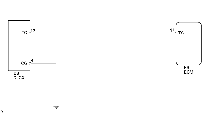
WIRING DIAGRAM
INSPECTION PROCEDURE
CHECK DLC3 (TC VOLTAGE)
CHECK HARNESS AND CONNECTOR (DLC3 - ECM)
CHECK IF MIL BLINKS
SFI SYSTEM - TC and CG Terminal Circuit |
DESCRIPTION
Terminals TC and CG are located in the DLC3. When connecting these terminals, DTCs in normal mode or check mode can be determined through MIL flashing patterns in the combination meter.
WIRING DIAGRAM
INSPECTION PROCEDURE
- HINT:
- If either of the following symptoms is present, it is determined that an open or a short in the wire harness has occurred, or there has been a malfunction in the ECM.
- The MIL displaying function does not work even though terminals TC and CG of the DLC3 are connected.
- The MIL flashes even though terminals TC and CG of the DLC3 are not connected.
| 1.CHECK DLC3 (TC VOLTAGE) |
Turn the ignition switch ON.
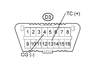
Measure the voltage of the DLC3.
- Standard voltage:
Tester Connection
| Specified Condition
|
D3-13 (TC) - D3-4 (CG)
| 9 to 14 V
|
| 2.CHECK HARNESS AND CONNECTOR (DLC3 - ECM) |
Disconnect the E9 ECM connector.
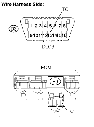
Measure the resistance of the wire harness side connectors.
- Standard resistance:
Tester Connection
| Specified Condition
|
D3-13 (TC) - E9-17 (TC)
| Below 1 Ω
|
D3-13 (TC) or E9-17 (TC) - Body ground
| 10 kΩ or higher
|
| | REPAIR OR REPLACE HARNESS OR CONNECTOR |
|
|
| OK |
|
|
|
| REPAIR OR REPLACE HARNESS OR CONNECTOR (DLC3 - BODY GROUND) |
|
Turn the ignition switch ON.
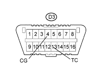
Using SST, connect terminals TC and CG of the D3 DLC3 connector.
- SST
- 09843-18040
Check that the MIL blinks.
- OK:
- The MIL blinks.