Sfi System Ecm Back-Up Power Source Circuit
DESCRIPTION
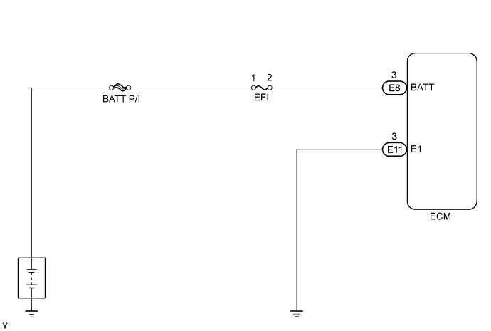
WIRING DIAGRAM
INSPECTION PROCEDURE
INSPECT FUSE (EFI)
CHECK ECM (BATT VOLTAGE)
CHECK HARNESS AND CONNECTOR (ECM - EFI FUSE, EFI FUSE - BATTERY)
SFI SYSTEM - ECM Back-up Power Source Circuit |
DESCRIPTION
While the ignition switch is OFF, battery voltage is supplied to terminal BATT of the ECM for the DTC memory, air-fuel ratio adaptive control value memory, etc.
WIRING DIAGRAM
INSPECTION PROCEDURE
Remove the EFI fuse from the engine room junction block.
Measure the resistance of the fuse.
- Standard resistance:
- Below 1 Ω
| | CHECK FOR SHORT IN ALL HARNESSES AND COMPONENTS CONNECTED TO FUSE |
|
|
| 2.CHECK ECM (BATT VOLTAGE) |
Turn the ignition switch ON.
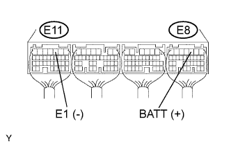
Measure the voltage of the ECM connectors.
- Standard voltage:
Tester Connection
| Specified Condition
|
E8-3 (BATT) - E11-3 (E1)
| 8 to 14 V
|
| 3.CHECK HARNESS AND CONNECTOR (ECM - EFI FUSE, EFI FUSE - BATTERY) |
Check the wire harness between the EFI fuse and ECM.
Remove the EFI fuse from the engine room junction block.
Disconnect the E8 ECM connector.
Measure the resistance of the wire harness side connectors.
- Standard resistance:
Tester Connection
| Specified Condition
|
J/B EFI fuse terminal 2 - E8-3 (BATT)
| Below 1 Ω
|
J/B EFI fuse terminal 2 or E8-3 (BATT) - Body ground
| 10 kΩ or higher
|
Check the wire harness between the EFI fuse and battery.
Remove the EFI fuse from the engine room junction block.
Disconnect the positive (+) battery cable.
Measure the resistance of the wire harness side connectors.
- Standard resistance:
Tester Connection
| Specified Condition
|
Positive (+) battery cable - J/B EFI fuse terminal 1
| Below 1 Ω
|
Positive (+) battery cable or J/B EFI fuse terminal 1 -
Body ground
| 10 kΩ or higher
|
| | REPAIR OR REPLACE HARNESS OR CONNECTOR |
|
|
| OK |
|
|
|
| REPLACE ENGINE ROOM RELAY BLOCK |
|