Wiper And Washer System (W/ Rain Sensor) - Headlight Cleaner Switch Circuit
DESCRIPTION
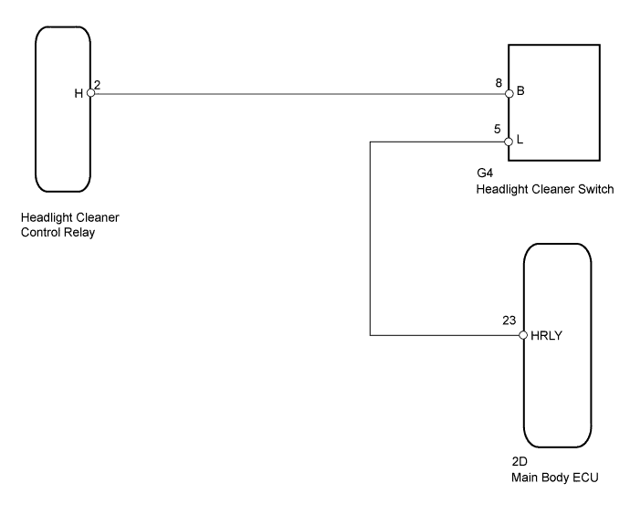
WIRING DIAGRAM
INSPECTION PROCEDURE
CHECK HEADLIGHT ASSEMBLY (LO BEAM)
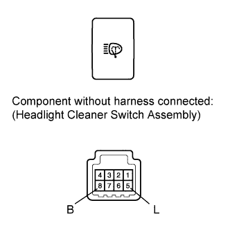
INSPECT HEADLIGHT CLEANER SWITCH ASSEMBLY
CHECK HARNESS AND CONNECTOR (HEADLIGHT CLEANER SWITCH ASSEMBLY - HEADLIGHT CLEANER CONTROL RELAY AND MAIN BODY ECU)
WIPER AND WASHER SYSTEM (w/ Rain Sensor) - Headlight Cleaner Switch Circuit
DESCRIPTION
This circuit detects the conditions of the headlight cleaner switch.
Headlight cleaner switch signal
Headlight operating signal
Daytime running light operating signal
WIRING DIAGRAM
INSPECTION PROCEDURE
| 1.CHECK HEADLIGHT ASSEMBLY (LO BEAM) |
Check that the headlights illuminate in LO beam.
- OK:
- Headlights illuminate in LO beam
| 2.INSPECT HEADLIGHT CLEANER SWITCH ASSEMBLY |
Disconnect the G4 cleaner switch connector.
Measure the resistance according to the value(s) in the table below.
- Standard Resistance:
| Tester Connection | Condition | Specified Condition |
| 8 (B) - 5 (L) | Headlight cleaner switch off | 10 kΩ or higher |
| 8 (B) - 5 (L) | Headlight cleaner switch on | Below 1 Ω |
| | REPLACE HEADLIGHT CLEANER SWITCH ASSEMBLY ()
|
|
|
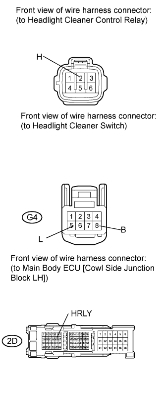
| 3.CHECK HARNESS AND CONNECTOR (HEADLIGHT CLEANER SWITCH ASSEMBLY - HEADLIGHT CLEANER CONTROL RELAY AND MAIN BODY ECU) |
Disconnect the headlight cleaner control relay connector.
Disconnect the G4 switch connector.
Disconnect the 2D main body ECU connector.
Measure the resistance according to the value(s) in the table below.
- Standard Resistance:
| Tester Connection | Condition | Specified Condition |
| 2 (H) - G4-8 (B) | Always | Below 1 Ω |
| G4-5 (L) - 2D-23 (HRLY) |
| 2 (H) - Body ground | Always | 10 kΩ or higher |
| G4-8 (B) - Body ground |
| G4-5 (L) - Body ground |
| 2D-23 (HRLY) - Body ground |
| | REPAIR OR REPLACE HARNESS OR CONNECTOR |
|
|
| OK | |
| |
| REPLACE HEADLIGHT CLEANER CONTROL RELAY ()
|
|