Land Cruiser URJ200 URJ202 GRJ200 VDJ200 - DOOR / HATCH
BACK DOOR - REASSEMBLY
| 1. INSTALL BACK DOOR DAMPER ASSEMBLY (w/ Power Back Door) |

When reusing the back door damper assembly:
Install the back door damper assembly with the bolt.
- Torque:
- 7.5 N*m{ 76 kgf*cm, 66 in.*lbf}
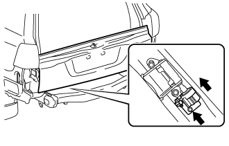
When installing a new back door damper assembly:
With closing the tail gate, install a new back door damper assembly with the bolt.
- Torque:
- 7.5 N*m{ 76 kgf*cm, 66 in.*lbf}
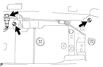
| 2. INSTALL TAIL GATE STAY SUB-ASSEMBLY LH |
Clean the threaded surface on the vehicle body with a non-residue solvent.
Apply adhesive to the threads of the screws.
- Adhesive:
- Toyota Genuine Adhesive 1324, Three Bond 1324 or equivalent
Using a T40 "TORX" wrench, install the 2 screws and tail gate stay.
| 3. INSTALL TAIL GATE STAY SUB-ASSEMBLY RH |
- HINT:
- Use the same procedure described for the LH side.
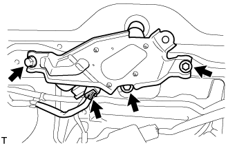
| 4. INSTALL LOWER TAIL GATE LOCK ASSEMBLY LH |
w/o Power Back Door:
Using a T30 "TORX" wrench, install the 3 screws and lower tail gate lock assembly LH.
- Torque:
- 5.0 N*m{ 51 kgf*cm, 44 in.*lbf}
w/ Power Back Door:
Using a T30 "TORX" wrench, install the 4 screws and lower tail gate lock assembly LH.
- Torque:
- 5.0 N*m{ 51 kgf*cm, 44 in.*lbf}
Connect the connector.
| 5. INSTALL BACK DOOR REMOTE CONTROL ASSEMBLY |
w/o Power Back Door:
Connect the left side cable.
Using a T30 "TORX" wrench, install the 2 screws and back door remote control assembly.
- Torque:
- 5.0 N*m{ 51 kgf*cm, 44 in.*lbf}
w/ Power Back Door:
Connect the connector.
Using a T30 "TORX" wrench, install the 2 screws and back door remote control assembly.
- Torque:
- 5.0 N*m{ 51 kgf*cm, 44 in.*lbf}
| 6. INSTALL LOWER TAIL GATE LOCK ASSEMBLY RH |
w/o Power Back Door:
Connect the cable to the lower tail gate lock assembly RH.
Using a T30 "TORX" wrench, install the 3 screws and lower tail gate lock assembly RH.
- Torque:
- 5.0 N*m{ 51 kgf*cm, 44 in.*lbf}
w/ Power Back Door:
Using a T30 "TORX" wrench, install the 4 screws and lower tail gate lock assembly RH.
- Torque:
- 5.0 N*m{ 51 kgf*cm, 44 in.*lbf}
Connect the connector.
| 7. INSTALL BACK DOOR INSIDE HANDLE ASSEMBLY |
Install the back door handle grommet.
Install the screw and back door inside handle assembly.
- Torque:
- 5.0 N*m{ 51 kgf*cm, 44 in.*lbf}
| 8. INSTALL BACK DOOR TORSION BAR GUIDE |
Attach the 2 claws to install the back door torsion bar guide.
| 9. INSTALL LOWER BACK DOOR TORSION BAR ASSEMBLY |
Install the 4 bolts and lower back door torsion bar assembly.
- Torque:
- 7.5 N*m{ 76 kgf*cm, 66 in.*lbf}
| 10. INSTALL SPARE TIRE |
| 11. INSTALL REAR BUMPER ASSEMBLY |
for Standard:
Install the rear bumper assembly ().
w/ Towing Hitch:
Install the rear bumper assembly ().
w/ Pintle Hook:
Install the rear bumper assembly ().
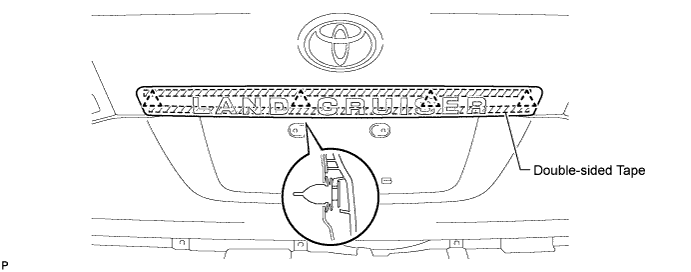
| 12. INSTALL REAR LICENSE LIGHT COVER (w/ Tire Carrier) |
Clean the vehicle body surface.
Using a heat light, heat the vehicle body surface.
Remove the double-sided tape from the vehicle body.
Wipe off any tape adhesive residue with cleaner.
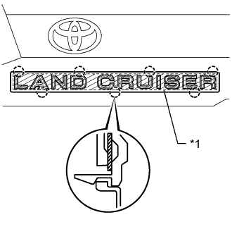
Install a new rear license light cover.
| *1 | Double-sided Tape |
Using a heat light, heat the vehicle body and a new rear license light cover.
Remove the peeling paper from the face of the emblem.
- HINT:
- After removing the peeling paper, keep the exposed adhesive free from foreign matter.
Attach the 7 claws to install the rear license light cover.
- HINT:
- Press the rear license light cover firmly to install it.
| 13. INSTALL LICENSE PLATE LIGHT ASSEMBLY (w/ Tire Carrier) |
Install the 2 license plate lights with the 2 screws.
| 14. INSTALL NO. 2 BACK DOOR OUTSIDE GARNISH SUB-ASSEMBLY (w/ Tire Carrier) |
Pass the wire harness of the license plate light through the tail gate, and install the wire harness.
Attach the 7 clips to install the No. 2 back door garnish.
Install the 2 nuts and connect the connector.
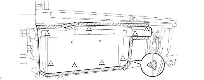
| 15. INSTALL BACK DOOR TRIM PANEL ASSEMBLY |
Attach the 16 clips to install the back door trim panel assembly.
Install the 4 bolts.
| 16. INSTALL BACK DOOR TRIM COVER RH |
Install the back door trim cover RH as shown in the illustration.
| 17. INSTALL BACK DOOR TRIM COVER LH |
Install the back door trim cover LH as shown in the illustration.
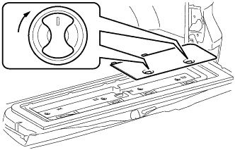
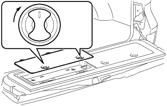
| 18. INSTALL REAR FLOOR MAT REAR SUPPORT PLATE |
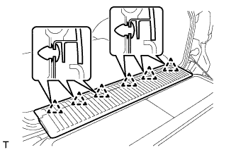
Attach the 6 clips to install the support plate.
| 19. INSTALL BACK DOOR STAY ASSEMBLY LH |
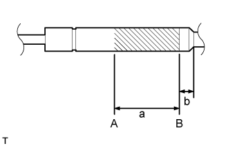
Horizontally fix the stay in a vise with the piston-rod pulled out.
Using a metal saw, gradually cut any area between A and B to release the gas.
- Standard Measurement:
Area Specified Condition a 150 mm (5.91 in.) b 20 mm (0.787 in.)
- CAUTION:
- As metal debris may be blown outward by the gas, you must:
- NOTICE:
- The gas inside the hood support is colorless, odorless and harmless. As there is a possibility that metal debris could scatter, cover the back door stay with a piece of cloth or other material.
| 20. INSTALL BACK DOOR STAY ASSEMBLY RH |
- HINT:
- Use the same procedure described for the LH side.
| 21. INSTALL REAR WASHER NOZZLE (w/ Rear Wiper) |
Attach the 2 claws to install the rear washer nozzle.

Connect the washer hose.
| 22. INSTALL REAR SPOILER SUB-ASSEMBLY (w/ Rear Spoiler) |
Attach the 3 clips to install the rear spoiler sub-assembly.
w/ Power Back Door:
Install the 4 bolts and 2 hole plugs.
w/o Power Back Door:
Install the 4 bolts.
| 23. INSTALL BACK DOOR GLASS CHANNEL LH (w/o Power Back Door) |

Attach the clip and install the back door glass channel.
| 24. INSTALL BACK DOOR GLASS CHANNEL RH (w/o Power Back Door) |
- HINT:
- Use the same procedure described for the LH side.
| 25. INSTALL BACK DOOR OUTSIDE GARNISH SUB-ASSEMBLY |
Clean the vehicle body surface.
Using a heat light, heat the vehicle body surface.
Remove the double-sided tape from the vehicle body surface.
Wipe off any tape adhesive residue with cleaner.
Install a new back door garnish.
Using a heat light, heat a new back door garnish and the vehicle body surface.
Remove the peeling paper from the face of the back door garnish.
- HINT:
- After removing the peeling paper, keep the exposed adhesive free from foreign matter.
Attach the 4 clips and double-sided tape to install the back door garnish.
- HINT:
- Press the back door garnish firmly to install it.
| 26. INSTALL LOWER BACK DOOR STOPPER |
Install the bolt and lower back door stopper.
| 27. INSTALL CUSHION |
Install the 2 cushions.
| 28. INSTALL LIFT GATE WEATHERSTRIP |
Attach the 25 clips to install the lift gate weatherstrip.
- NOTICE:
- Do not pull strongly on the lift gate weatherstrip as it may tear.
| 29. INSTALL REAR TELEVISION CAMERA ASSEMBLY (w/ Parking Assist Monitor System or Rear View Monitor System) |
Connect the connector.
Attach the 4 claws to install the rear television camera assembly.

Using a T30 "TORX" socket wrench, install the rear television camera with the 2 screws.
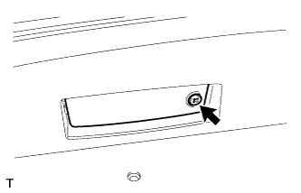
| 30. INSTALL BACK DOOR OPENER SWITCH ASSEMBLY |
Connect the connector.
Install the back door opener switch assembly with the 2 screws.
- Torque:
- 5.0 N*m{ 51 kgf*cm, 44 in.*lbf}
| 31. INSTALL LICENSE PLATE LIGHT LENS (for Standard) |

Connect the connector.
Attach the 2 claws in the order shown in the illustration to install the license plate light.
| 32. INSTALL BACK DOOR CONTROL SWITCH (w/ Power Back Door) |
Attach the 4 claws to install the back door control switch.
Connect the connector.
| 33. INSTALL BACK DOOR LOCK PROTECTOR (w/ Power Back Door) |
Attach the 2 claws to install the protector (A).
Attach the 7 claws to install the protector (B).
Install the screw.
| 34. INSTALL BACK DOOR LOCK ASSEMBLY |
w/o Power Back Door:
Install the back door lock assembly with the 3 bolts.
- Torque:
- 13 N*m{ 133 kgf*cm, 10 ft.*lbf}
Connect the connector.
w/ Power Back Door:
Install the back door lock assembly with the 4 bolts.
- Torque:
- 13 N*m{ 133 kgf*cm, 10 ft.*lbf}
Attach the guide.
Connect the connector.
| 35. INSTALL BACK DOOR LOCK COVER |
Attach the 4 claws to install the back door lock cover.
| 36. INSTALL REAR WIPER MOTOR ASSEMBLY (w/ Rear Wiper) |
Temporarily install the rear wiper motor assembly with the 3 bolts.
Tighten the 3 bolts.
- Torque:
- 5.5 N*m{ 56 kgf*cm, 49 in.*lbf}
Connect the connector.
| 37. INSTALL REAR WIPER MOTOR GROMMET (w/ Rear Wiper) |
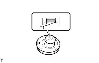
Apply MP grease to the entire inner surface of the rear wiper motor grommet.
| *1 | MP Grease |
- HINT:
- Make sure that the hole does not get clogged with grease and the grooves in the grommet are filled with grease.

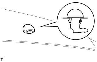
Install the rear wiper motor grommet with the position mark facing upward as shown in the illustration.
| *1 | Position Mark |
| 38. INSTALL REAR WIPER ARM (w/ Rear Wiper) |
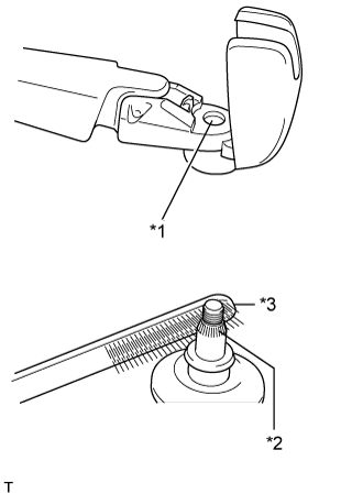
Operate the rear wiper, and stop the rear wiper motor at the automatic stop position.
| *1 | Wiper Arm Serration |
| *2 | Wiper Pivot Serration |
| *3 | Wire Brush |
Clean the wiper arm serration and wiper pivot serration with a wire brush.

Set the head of the blade on the defogger line.
| *1 | Defogger Line |
Install the nut and rear wiper arm.
- Torque:
- 5.5 N*m{ 56 kgf*cm, 49 in.*lbf}
Close the cover.
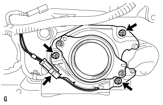
| 39. INSTALL POWER BACK DOOR SENSOR ASSEMBLY LH (w/ Power Back Door) |
Attach the 2 clips to install the power back door sensor assembly LH.
Using a T25 "TORX" wrench, install the 6 screws.
Connect the connector.
| 40. INSTALL POWER BACK DOOR SENSOR ASSEMBLY RH (w/ Power Back Door) |
- HINT:
- Use the same procedure described for the LH side.
| 41. INSTALL REAR ASSIST GRIP REINFORCEMENT (for Face to Face Seat Type) |
Attach the 2 claws to install the rear assist grip reinforcement.
Install the 3 bolts.
| 42. INSTALL REAR HEADER SPEAKER ASSEMBLY (for 14 Speakers) |
Connect the connector.
Install the rear header speaker assembly with the 3 screws.
| 43. INSTALL BACK DOOR GARNISH |
Attach the 14 clips to install the back door garnish.
| 44. INSTALL DOOR OPENING SWITCH SUB-ASSEMBLY (for Face to Face Seat Type) |
Attach the 2 claws to install the door opening switch sub-assembly.
| 45. INSTALL NO. 2 BACK DOOR SERVICE HOLE COVER (for Face to Face Seat Type) |
Connect the connector.
Attach the 4 claws to install the No. 2 back door service hole cover.
| 46. INSTALL ASSIST GRIP (for Face to Face Seat Type) |
Install the assist grip with the 2 screws.
| 47. INSTALL BACK DOOR SERVICE HOLE COVER RH (w/ Power Back Door) |

Install the back door stay plate.

Pass the power back door rod through the hole of the back door service hole cover RH and install the rod with the bolt.
- Torque:
- :
- 18 N*m{ 184 kgf*cm, 13 ft.*lbf}
Move the back door to a half-open position so that the hole in the center of the back door service hole cover RH is aligned lengthwise with the power back door rod.
Attach the 2 clips and install the back door service hole cover RH.
- NOTICE:
- If the back door is in a fully-open position, the power back door rod will interfere with the hole of the back door service hole cover, so do not perform this operation with the back door in a fully open position.
| 48. INSTALL BACK DOOR SIDE GARNISH LH |
Attach the 3 clips and 2 claws to install the back door side garnish LH.
| 49. INSTALL BACK DOOR SIDE GARNISH RH |
w/o Power Back Door:
- HINT:
- Use the same procedure described for the LH side.
w/ Power Back Door:
Attach the clip and 4 claws to install the back door side garnish RH.
| 50. INSTALL CENTER STOP LIGHT ASSEMBLY |

Attach the 2 claws to install the stop light.
| 51. INSTALL CENTER BACK DOOR GARNISH |
Attach the 5 clips and 4 claws to install the center back door garnish.
| 52. INSTALL LOWER BACK DOOR STOPPER CUSHION |
Install the 2 lower back door stopper cushions with the 4 bolts.
| 53. INSTALL BACK DOOR GRIP |
Attach the claw.
Install the back door grip with the 2 screws.
Attach the 5 claws to close the cover.
| 54. CONNECT CABLE TO NEGATIVE BATTERY TERMINAL |
- NOTICE:
- When disconnecting the cable, some systems need to be initialized after the cable is reconnected ().
| 55. ADJUST REAR TELEVISION CAMERA ASSEMBLY |
w/o Side Monitor System:
()
w/ Side Monitor System:
()