Power Back Door System - Ecu Power Source Circuit
DESCRIPTION
WIRING DIAGRAM
INSPECTION PROCEDURE
CHECK HARNESS AND CONNECTOR (POWER BACK DOOR UNIT ASSEMBLY [POWER BACK DOOR ECU] - BATTERY AND BODY GROUND)
POWER BACK DOOR SYSTEM - ECU Power Source Circuit
DESCRIPTION
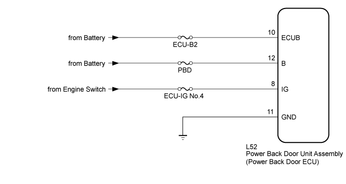
This circuit supplies power to operate the power back door unit assembly (power back door ECU).
WIRING DIAGRAM
INSPECTION PROCEDURE
- Inspect the fuses for circuits related to this system before performing the following inspection procedure.
| 1.CHECK HARNESS AND CONNECTOR (POWER BACK DOOR UNIT ASSEMBLY [POWER BACK DOOR ECU] - BATTERY AND BODY GROUND) |
Disconnect the power back door unit assembly (power back door ECU) connector.
Measure the voltage according to the value(s) in the table below.
- Standard Voltage:
| Tester Connection | Condition | Specified Condition |
| L52-10 (ECUB) - Body ground | Always | 11 to 14 V |
| L52-12 (B) - Body ground | Always | 11 to 14 V |
| L52-8 (IG) - Body ground | Engine switch on (IG) | 11 to 14 V |
| L52-8 (IG) - Body ground | Engine switch off | Below 1 V |
Measure the resistance according to the value(s) in the table below.
- Standard Resistance:
| Tester Connection | Condition | Specified Condition |
| L52-11 (GND) - Body ground | Always | Below 1 Ω |
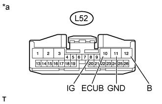
Text in Illustration| *a | Front view of wire harness connector
(to Power Back Door Unit Assembly [Power Back Door ECU]) |
| | REPAIR OR REPLACE HARNESS OR CONNECTOR |
|
|
| OK | |
| |
| PROCEED TO NEXT SUSPECTED AREA SHOWN IN PROBLEM SYMPTOMS TABLE ()
|
|