Land Cruiser URJ200 URJ202 GRJ200 VDJ200 - INTERIOR PANELS / TRIM
FRONT CONSOLE BOX (w/ Cool Box) - INSPECTION
| 1. INSPECT COOLER CONTROL SWITCH SUB-ASSEMBLY |
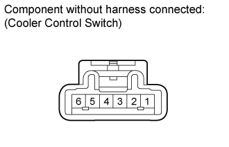
Measure the resistance according to the value(s) in the table below.
- Standard Resistance:
Tester Connection Switch Condition Specified Condition 1 - 2 On Below 1 Ω 1 - 2 Off 10 kΩ or higher
Apply battery voltage to the cooler control switch connector and check that the indicator illuminates.
- OK:
Measurement Condition Specified Condition Battery positive (+) → Terminal 3
Battery negative (-) → Terminal 4indicator illuminates
If the result is not as specified, replace the cooler control switch.
| 2. INSPECT NO. 1 COOLER BLOWER MOTOR SUB-ASSEMBLY |
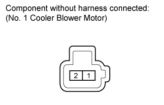
Apply battery voltage to the blower motor connector and check the operation of the blower motor.
- OK:
Measurement Condition Specified Condition Battery positive (+) → Terminal 1
Battery negative (-) → Terminal 2Motor operates smoothly
If the result is not as specified, replace the blower motor.
| 3. INSPECT NO. 3 COOLER THERMISTOR |

Measure the resistance according to the value(s) in the table below.
- Standard Resistance:
Tester Connection Condition Specified Condition 1 - 2 -10°C (14°F) 7.40 to 9.20 kΩ 1 - 2 -5°C (23°F) 5.65 to 7.00 kΩ 1 - 2 0°C (32°F) 4.35 to 5.40 kΩ 1 - 2 5°C (41°F) 3.40 to 4.20 kΩ 1 - 2 10°C (50°F) 2.68 to 3.30 kΩ 1 - 2 15°C (59°F) 2.10 to 2.60 kΩ 1 - 2 20°C (68°F) 1.66 to 2.10 kΩ 1 - 2 25°C (77°F) 1.32 to 1.66 kΩ 1 - 2 30°C (86°F) 1.05 to 1.35 kΩ
- NOTICE:
Even slightly touching the sensor may change the resistance value. Be sure to hold the connector of the sensor.
When measuring, the sensor temperature must be the same as the ambient temperature.
- HINT:
As the temperature increases, the resistance decreases (see the graph).
If the result is not as specified, replace the cooler thermistor.