Rear View Monitor System -- Terminals Of Ecu |
| CHECK RADIO AND DISPLAY RECEIVER ASSEMBLY |
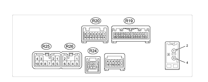
Disconnect the R19 and R25 radio and display receiver assembly connectors.
Measure the voltage and resistance according to the value(s) in the table below.
If the result is not as specified, there may be a malfunction on the wire harness side.Terminal No. (Symbol) Wiring Color Terminal Description Condition Specified Condition R19-1 (IG) - R25-7 (GND) P - BR IG signal Ignition switch off Below 1 V Ignition switch ON 11 to 14 V R25-3 (ACC) - R25-7 (GND) GR - BR Accessory (On) Ignition switch off Below 1 V Ignition switch ACC 11 to 14 V R25-4 (B) - R25-7 (GND) L-Y - BR Battery Always 11 to 14 V R25-7 (GND) - Body ground BR - Body ground Ground Always Below 1 Ω Reconnect the R19 and R25 radio and display receiver assembly connectors.
Measure the voltage according to the value(s) in the table below.
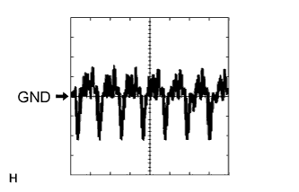
If the result is not as specified, the radio and display receiver assembly may have a malfunction.Terminal No. (Symbol) Wiring Color Terminal Description Condition Specified Condition R19-2 (REV) - R25-7 (GND) R-Y - BR Reverse signal Ignition switch ON, shift lever in R 7.5 to 14 V Ignition switch ON, shift lever not in R Below 1 V R20-7 (CA+) - R20-15 (CGND) B - Shielded Power source Ignition switch ON, shift lever in R 5.5 to 7.05 V R20-8 (V+) - R20-16 (V-) W - R Display signal Ignition switch ON, shift lever in R Pulse generation
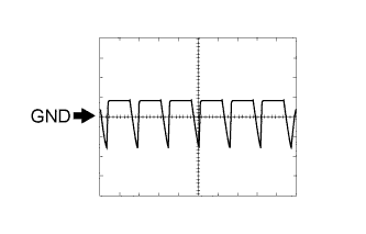
(See waveform 1)Ignition switch ON, shift lever in R, screen blacked out by covering camera lens Pulse generation
(See waveform 2)R20-15 (CGND) - Body ground Shielded - Body ground Shielding Always Below 1 V Using an oscilloscope, check waveform 1.
Measurement Condition Item Content Terminal No. (Symbol) R20-8 (V+) - R20-16 (V-) Tool Setting 0.2 V/DIV., 50 μs/DIV. Condition Ignition switch ON, shift lever in R Using an oscilloscope, check waveform 2.
Measurement Condition Item Content Terminal No. (Symbol) R20-8 (V+) - R20-16 (V-) Tool Setting 0.2 V/DIV., 50 μs/DIV. Condition Ignition switch ON, shift lever in R, screen blacked out by covering camera lens
 |
 |