Air Conditioning System (For Automatic Air Conditioning System) -- System Description |
| GENERAL |
The air conditioning system has the following features:
- The air conditioning amplifier is equipped with a self-diagnosis function. If there is a malfunction in the system, it stores DTC(s) in its memory and the air conditioning switch indicator blinks.
- The air conditioning amplifier receives the vehicle speed signal from the combination meter.
- The damper servo (air inlet damper servo motor), air mix damper servo and mode damper servo (air vent damper servo motor) rely on their built-in pulse sensors to detect their respective motor rotation angles.
- The servo motor rotation angle's zero point calibration is necessary in the following situations: 1) the servo motor deviates from the calibrated position, 2) the air conditioning amplifier's backup power source is cut, or 3) the air conditioning amplifier or servo motor is replaced.
For 1, when the ignition switch is turned off, zero point calibration of the air conditioning amplifier is automatically performed. For 2 and 3, when the backup power source returns and the ignition switch is turned to ON, zero point calibration of the air conditioning amplifier is automatically performed.
While zero point calibration is being performed, the following occurs: 1) the air conditioning amplifier's DEF indicator blinks at 1 second intervals, but the air conditioning amplifier's other outputs are disabled; and 2) the A/C system's switches do not function. - The cooling (rear) unit is mounted inside the right rear quarter trim.
- The blower motor of the rear cooler can be operated with the cooler control switch only when the cooler (rear) switch is ON.
- When the front air conditioning is not operating, the rear cooler can only blow out air.
- The air conditioning amplifier is equipped with a self-diagnosis function. If there is a malfunction in the system, it stores DTC(s) in its memory and the air conditioning switch indicator blinks.
| MODE POSITION AND DAMPER OPERATION |
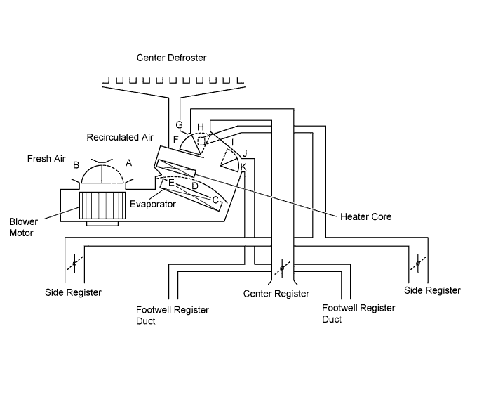
| Control Damper | Control Position | Damper Position | Operation | |
| Air Inlet Control Damper |  FRESH | A | Brings in fresh air. | |
 RECIRCULATION | B | Recirculates internal air. | ||
| Air Mix Control Damper | MAX COLD - MAX HOT | C, D, E | Varies mixture ratio of cool air and warm air in order to regulate temperature continuously from HOT to COLD. | |
| Mode Control Damper |  DEF | H, K | Defrosts windshield through center defroster and side registers. | |
 FOOT / DEF | H, I | Defrosts windshield through center defroster and side registers. Air is also blown out from footwell register ducts. | ||
 FOOT | G, I | Air blows out of footwell register ducts and side registers. Air also blows out slightly from center defroster. | ||
 BI - LEVEL | F, J | Air blows out of center register, side registers and footwell register ducts. | ||
 FACE | F, K | Air blows out of center register and side registers. | ||
| AIR OUTLETS AND AIR FLOW VOLUME |
| Air Outlet Mode | A | B | C | D | |
| Center Face | Side Face | Foot | Defroster | ||
| Face | |  | |  | |
| BI-LEVEL | | | |  | |
| FOOT | | | | | |
| FOOT / DEF | | | | | |
| DEF | | | | | |
- HINT:
- The circle size (○) is proportional to the amount of air flow.