Symbols (Terminal No.)
| Wiring Color
| Terminal Description
| Condition
| Specified Condition
|
AIR (A16-22) - GND (A16-1)
| L-W - L
| Air inlet damper servo motor operation voltage
| Ignition switch ON
Fresh switch ON
| Below 1 V
|
AIR (A16-22) - GND (A16-1)
| L-W - L
| Air inlet damper servo motor operation voltage
| Ignition switch ON
Recirculation switch ON
| 11 to 14 V
|
AIF (A16-23) - GND (A16-1)
| G-Y - L
| Air inlet damper servo motor operation voltage
| Ignition switch ON
Recirculation switch ON
| Below 1 V
|
AIF (A16-23) - GND (A16-1)
| G-Y - L
| Air inlet damper servo motor operation voltage
| Ignition switch ON
Fresh switch ON
| 11 to 14 V
|
AOF (A16-3) - GND (A16-1)
| Y-B - L
| Air vent mode damper servo motor operation voltage
| Ignition switch ON
Mode switch DEF
| Below 1 V
|
AOF (A16-3) - GND (A16-1)
| Y-B - L
| Air vent mode damper servo motor operation voltage
| Ignition switch ON
Mode switch FACE
| 11 to 14 V
|
AOD (A16-4) - GND (A16-1)
| R-B - L
| Air vent mode damper servo motor operation voltage
| Ignition switch ON
Mode switch FACE
| Below 1 V
|
AOD (A16-4) - GND (A16-1)
| R-B - L
| Air vent mode damper servo motor operation voltage
| Ignition switch ON
Mode switch DEF
| 11 to 14 V
|
PIA (A15-17) - SG-7 (A15-21)
| P-B - LG-R
| Input signal for pulse position sensor (Air inlet damper servo motor)
| Ignition switch ON
Air inlet control:
Changed from RECIRCULATION to FRESH or vice versa
| Pulse generation
|
PIB (A15-16) - SG-7 (A15-21)
| R-L - LG-R
| Input signal for pulse position sensor (Air inlet damper servo motor)
| Ignition switch ON
Air inlet control:
Changed from RECIRCULATION to FRESH or vice versa
| Pulse generation
|
SG-7 (A15-21) - Body ground
| LG-R - Body ground
| Ground for pulse position sensor (Air inlet damper servo motor)
| Always
| Below 1 Ω
|
POA (A15-26) - SG-2 (A15-11)
| L-O - L-Y
| Input signal for pulse position sensor (Air vent mode damper servo motor)
| Ignition switch ON
Mode control:
Changed from FACE to DEF or vice versa
| Pulse generation
|
POB (A15-25) - SG-2 (A15-11)
| LG - L-Y
| Input signal for pulse position sensor (Air vent mode damper servo motor)
| Ignition switch ON
Mode control:
Changed from FACE to DEF or vice versa
| Pulse generation
|
SG-2 (A15-11) - Body ground
| L-Y - Body ground
| Ground for pulse position sensor (Air vent mode damper servo motor)
| Always
| Below 1 Ω
|
TE (A15-1) - SG-4 (A15-14)
| G - P
| A/C evaporator temperature sensor signal
| Ignition switch ON
Evaporator temperature:
0°C (32°F)
| 2 to 2.4 V
|
TE (A15-1) - SG-4 (A15-14)
| G - P
| A/C evaporator temperature sensor signal
| Ignition switch ON
Evaporator temperature:
15°C (59°F)
| 1.4 to 1.8 V
|
SG-4 (A15-14) - Body ground
| P - Body ground
| Ground for A/C evaporator temperature sensor
| Always
| Below 1 Ω
|
IG+ (A16-6) - GND (A16-1)
| R-L - L
| Power source (IG)
| Ignition switch off or ACC
| Below 1 V
|
IG+ (A16-6) - GND (A16-1)
| R-L - L
| Power source (IG)
| Ignition switch ON
| 11 to 14 V
|
+B1 (A16-5) - GND (A16-1)
| L-Y - L
| Power source (Back-up)
| Always
| 11 to 14 V
|
GND (A16-1) - Body ground
| L - Body ground
| Ground for main power supply
| Always
| Below 1 Ω
|
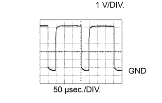
BLW (A16-2) - GND (A16-1)
| L-B - L
| Blower motor speed control voltage
| Ignition switch ON
Blower switch ON (LO)
| Pulse generation
(see waveform 1)
|
TS (A15-7) - S5-3 (A15-2)
| L-W - W-R
| A/C solar sensor signal
| Ignition switch ON
| 0.8 to 4.3 V
|
S5-3 (A15-2) - GND (A16-1)
| W-R - L
| Power supply for solar sensor
| Ignition switch ON
| 4.5 to 5.5 V
|
HR (A16-14) - GND (A16-1)
| L-W - L
| HTR relay signal
| Ignition switch ON
Blower switch OFF
| 11 to 14 V
|
HR (A16-14) - GND (A16-1)
| L-W - L
| HTR relay signal
| Ignition switch ON
Blower switch ON
| Below 1 V
|
TR (A15-18) - SG-3 (A15-13)
| GR - BR-Y
| A/C room temperature sensor signal
| Ignition switch ON
Cabin temperature:
25°C (77°F)
| 1.8 to 2.2 V
|
TR (A15-18) - SG-3 (A15-13)
| GR - BR-Y
| A/C room temperature sensor signal
| Ignition switch ON
Cabin temperature:
40°C (104°F)
| 1.2 to 1.6 V
|
SG-3 (A15-13) - Body ground
| BR-Y - Body ground
| Ground for A/C room temperature sensor
| Always
| Below 1 Ω
|
RDFG (A16-12) - GND (A16-1)
| R-L - L
| Rear defogger switch signal
| Ignition switch ON
Rear defogger switch OFF
| 11 to 14 V
|
RDFG (A16-12) - GND (A16-1)
| R-L - L
| Rear defogger switch signal
| Ignition switch ON
Rear defogger switch ON
| Below 1 V
|
ACT (A16-7) - GND (A16-1)
| R-L - L
| Magnet clutch on permit input signal
| Ignition switch START
Magnet clutch ON: Not permitted
| Below 1 V
|
ACT (A16-7) - GND (A16-1)
| R-L - L
| Magnet clutch on permit input signal
| Ignition switch START
Magnet clutch ON: Permitted
| 11 to 14 V
|
AC1 (A16-21) - GND (A16-1)
| Y - L
| Idle-up request signal
| Ignition switch START
Magnet clutch: Not engaged
| 11 to 14 V
|
AC1 (A16-21) - GND (A16-1)
| Y - L
| Idle-up request signal
| Ignition switch START
Magnet clutch: Engaged
| Below 1 V
|
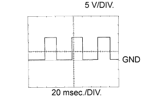
SPD (A16-9) - GND (A16-1)
| V-W - L
| Vehicle speed signal
| Driving at approx. 20 km/h (12 mph)
| Pulse generation
(see waveform 2)
|
PSW (A15-5) - GND (A16-1)
| Y-B - L
| Pressure switch signal
| Ignition switch START
Refrigerant pressure: Normal
| Below 1 V
|
PSW (A15-5) - GND (A16-1)
| Y-B - L
| Pressure switch signal
| Ignition switch START
Refrigerant pressure:
Less than 0.196 MPa (2.0 kgf/cm2, 28 psi) or more than 3.14 MPa (32.0 kgf/cm2, 455 psi)
| 11 to 14 V
|
TAMO (A16-18) - GND (A16-1)
| P - L
| A/C ambient temperature signal
| Ignition switch ON
| Pulse generation
|
MGC (A16-13) - GND (A16-1)
| B - L
| Magnet clutch signal
| Ignition switch START
Magnet clutch: Not engaged
| 11 to 14 V
|
MGC (A16-13) - GND (A16-1)
| B - L
| Magnet clutch signal
| Ignition switch START
Magnet clutch: Engaged
| Below 1 V
|
SW1 (A16-16) - GND (A16-1)
| G-O - L
| Hazard warning switch signal
| Hazard warning switch signal OFF
| 11 to 14 V
|
SW1 (A16-16) - GND (A16-1)
| G-O - L
| Hazard warning switch signal
| Hazard warning switch signal ON
| Below 1 V
|
ILL+ (A16-15) - GND (A16-1)
| G - L
| Power supply for illumination
| Light control switch OFF
| Below 1 V
|
ILL+ (A16-15) - GND (A16-1)
| G - L
| Power supply for illumination
| Light control switch TAIL
| 11 to 14 V
|
AMC (A16-19) - GND (A16-1)
| R-W - L
| Air mix damper servo motor operation signal
| Ignition switch ON
Temperature switch Max. HOT
| Below 1 V
|
AMC (A16-19) - GND (A16-1)
| R-W - L
| Air mix damper servo motor operation signal
| Ignition switch ON
Temperature switch Max. COOL
| 11 to 14 V
|
AMH (A16-17) - GND (A16-1)
| L - L
| Air mix damper servo motor operation signal
| Ignition switch ON
Temperature switch Max. HOT
| 11 to 14 V
|
AMH (A16-17) - GND (A16-1)
| L - L
| Air mix damper servo motor operation signal
| Ignition switch ON
Temperature switch Max. COOL
| Below 1 V
|
PMA (A15-24) - SG-1 (A15-20)
| W-R - BR-Y
| Input signal for pulse position sensor (Air mix damper servo motor)
| Ignition switch ON
Temperature switch: Max. COOL → Max. HOT
| Pulse generation
|
PMB (A15-23) - SG-1 (A15-20)
| W-L - BR-Y
| Input signal for pulse position sensor (Air mix damper servo motor)
| Ignition switch ON
Temperature switch: Max. HOT → Max. COOL
| Pulse generation
|
SG-1 (A15-20) - Body ground
| BR-Y - Body ground
| Ground for pulse position sensor (Air mix damper servo motor)
| Always
| Below 1 V
|
TW (A16-8) - GND (A16-1)
| P - L
| Engine coolant temperature sensor signal
| Ignition switch ON
| Pulse generation
|