Vehicle Stability Control System Abs Warning Light Remains On
DESCRIPTION
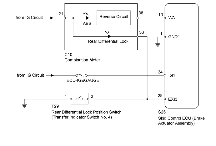
WIRING DIAGRAM
INSPECTION PROCEDURE
CHECK FOR DTC
CHECK IF SKID CONTROL ECU CONNECTOR IS SECURELY CONNECTED
CHECK HARNESS AND CONNECTOR (SKID CONTROL ECU IG1 TERMINAL)
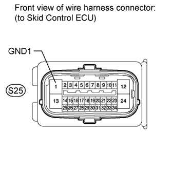
CHECK HARNESS AND CONNECTOR (SKID CONTROL ECU GND1 TERMINAL)
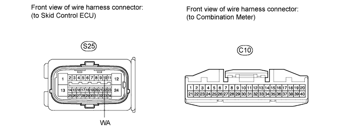
CHECK HARNESS AND CONNECTOR (SKID CONTROL ECU - COMBINATION METER)
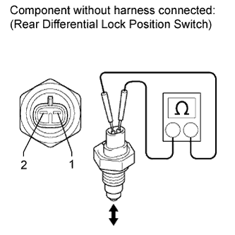
INSPECT TRANSFER INDICATOR SWITCH NO.4 (REAR DIFFERENTIAL LOCK POSITION SWITCH)
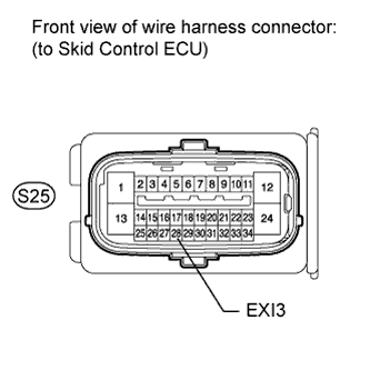
CHECK HARNESS AND CONNECTOR (SKID CONTROL ECU EXI3 TERMINAL)
READ VALUE USING INTELLIGENT TESTER (ABS WARNING LIGHT)
VEHICLE STABILITY CONTROL SYSTEM - ABS Warning Light Remains ON |
DESCRIPTION
When one of the following conditions is met, the ABS warning light remains on:- The skid control ECU connector is disconnected from the skid control ECU.
- There is a malfunction in the skid control ECU internal circuit.
- There is an open in the harness between the combination meter and the skid control ECU.
- The anti-lock brake system is defective.
WIRING DIAGRAM
INSPECTION PROCEDURE
- NOTICE:
- When replacing the brake actuator assembly, perform zero point calibration (Toyota Fortuner RM000000XHR02TX.html).
- Inspect the fuses for circuits related to this system before performing the following inspection procedure.
Check if DTCs for the ABS are recorded (Toyota Fortuner RM000000XHV03YX.html).
ResultResult
| Proceed to
|
DTC not output
| A
|
DTC output
| B
|
| | REPAIR CIRCUITS INDICATED BY OUTPUT DTCS |
|
|
| 2.CHECK IF SKID CONTROL ECU CONNECTOR IS SECURELY CONNECTED |
Check if the skid control ECU connector is securely connected.
- OK:
- The connector is securely connected.
| | CONNECT CONNECTOR TO ECU CORRECTLY |
|
|
| 3.CHECK HARNESS AND CONNECTOR (SKID CONTROL ECU IG1 TERMINAL) |
Turn the ignition switch off.
Disconnect the skid control ECU connector.
Measure the voltage according to the value(s) in the table below.
- Standard Voltage:
Tester Connection
| Switch Condition
| Specified Condition
|
S25-34 (IG1) - Body ground
| Ignition switch ON
| 11 to 14 V
|
| | REPAIR OR REPLACE HARNESS OR CONNECTOR |
|
|
| 4.CHECK HARNESS AND CONNECTOR (SKID CONTROL ECU GND1 TERMINAL) |
Turn the ignition switch off.
Disconnect the skid control ECU connector.
Measure the resistance according to the value(s) in the table below.
- Standard Resistance:
Tester Connection
| Condition
| Specified Condition
|
S25-1 (GND1) - Body ground
| Always
| Below 1 Ω
|
| | REPAIR OR REPLACE HARNESS OR CONNECTOR |
|
|
| 5.CHECK HARNESS AND CONNECTOR (SKID CONTROL ECU - COMBINATION METER) |
Turn the ignition switch off.
Disconnect the skid control ECU connector.
Disconnect the combination meter connector.
Measure the resistance according to the value(s) in the table below.
- Standard Resistance:
Tester Connection
| Condition
| Specified Condition
|
S25-10 (WA) - C10-38
| Always
| Below 1 Ω
|
S25-10 (WA) - Body ground
| Always
| 10 kΩ or higher
|
| | REPAIR OR REPLACE HARNESS OR CONNECTOR |
|
|
| 6.INSPECT TRANSFER INDICATOR SWITCH NO.4 (REAR DIFFERENTIAL LOCK POSITION SWITCH) |
Remove the rear differential lock position switch.
Measure the resistance according to the value(s) in the table below.
- Standard Resistance:
Tester Connection
| Switch Condition
| Specified Condition
|
1 - 2
| Pushed in
| Below 1 Ω
|
Released
| 10 kΩ or higher
|
| | REPLACE TRANSFER INDICATOR SWITCH NO.4 |
|
|
| 7.CHECK HARNESS AND CONNECTOR (SKID CONTROL ECU EXI3 TERMINAL) |
Turn the ignition switch off.
Disconnect the skid control ECU connector.
Measure the voltage according to the value(s) in the table below.
- Standard Voltage:
Tester Connection
| Switch Condition
| Specified Condition
|
S25-28 (EXI3) - Body ground
| Ignition switch ON
| 11 to 14 V
|
| | REPAIR OR REPLACE HARNESS OR CONNECTOR |
|
|
| 8.READ VALUE USING INTELLIGENT TESTER (ABS WARNING LIGHT) |
Turn the ignition switch off.
Connect the intelligent tester to the DLC3.
Turn the ignition switch to ON and the tester on.
Select the Data List mode on the intelligent tester (Toyota Fortuner RM000000XHW03RX.html).
ABS/VSC/TRCTester Display
| Measurement Item / Range
| Normal Condition
| Diagnostic Note
|
ABS Warning Light
| ABS warning light /
ON or OFF
| ON: ABS warning light ON
OFF: ABS warning light OFF
| -
|
Perform the Active Test of the skid control ECU using the intelligent tester (Toyota Fortuner RM000000XHW03RX.html).
ABS/VSC/TRCTester Display
| Test Part
| Control Range
| Diagnostic Note
|
ABS Warning Light
| ABS warning light
| Warning light ON / OFF
| Observe combination meter
|
ResultResult
| Proceed to
|
Data List Display
| Data List Display When Performing Active Test ON/OFF Operation
|
ON
| Does not change between ON and OFF
| A
|
Changes between ON and OFF
| B
|
OFF
| Does not change between ON and OFF
| A
|
Changes between ON and OFF
| B
|
| | REPLACE COMBINATION METER ASSEMBLY |
|
|
| A |
|
|
|
| REPLACE BRAKE ACTUATOR ASSEMBLY |
|