Dtc C1268/68 Transfer L4 Position Switch Circuit
DESCRIPTION
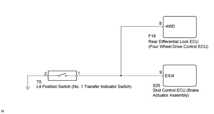
WIRING DIAGRAM
INSPECTION PROCEDURE
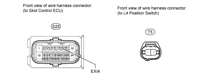
CHECK HARNESS AND CONNECTOR (SKID CONTROL ECU EXI4 TERMINAL)
RECONFIRM DTC
INSPECT L4 POSITION SWITCH (NO. 1 TRANSFER INDICATOR SWITCH)
CHECK HARNESS AND CONNECTOR (SKID CONTROL ECU - L4 POSITION SWITCH)
CHECK HARNESS AND CONNECTOR (SKID CONTROL ECU - REAR DIFFERENTIAL LOCK ECU)
DTC C1268/68 Transfer "L4" Position Switch Circuit |
DESCRIPTION
DTC Code
| DTC Detection Condition
| Trouble Area
|
C1268/68
| No signal is input to the EXI4 terminal of the skid control ECU.
| - L4 position switch (No. 1 transfer indicator switch)
- L4 position switch circuit
- Skid control ECU (Brake actuator assembly)
- Rear differential lock ECU (Four wheel drive control ECU)
|
WIRING DIAGRAM
INSPECTION PROCEDURE
- NOTICE:
- When replacing the brake actuator assembly, perform zero point calibration (Toyota Fortuner RM000000XHR02TX.html).
| 1.CHECK HARNESS AND CONNECTOR (SKID CONTROL ECU EXI4 TERMINAL) |
Turn the ignition switch off.
Disconnect the skid control ECU connector.
Measure the voltage according to the value(s) in the table below.
- Standard Voltage:
Tester Connection
| Condition
| Specified Condition
|
S25-9 (EXI4) - Body ground
| - Ignition switch ON
- Transfer sift position not LL
| 11 to 14 V
|
S25-9 (EXI4) - Body ground
| - Ignition switch ON
- Transfer sift position LL
| Below 1.5 V
|
Clear the DTC(s) (Toyota Fortuner RM000000XHV09NX.html).
Turn the ignition switch off.
Check if the same DTC is recorded.
ResultResult
| Proceed to
|
DTC is output
| A
|
DTC is not output
| B
|
| | USE SIMULATION METHOD TO CHECK |
|
|
| A |
|
|
|
| REPLACE BRAKE ACTUATOR ASSEMBLY |
|
| 3.INSPECT L4 POSITION SWITCH (NO. 1 TRANSFER INDICATOR SWITCH) |
Remove the L4 position switch.
Measure the resistance according to the value(s) in the table below.
- Standard Resistance:
Tester Connection
| Switch Condition
| Specified Condition
|
1 - 2
| Pushed
| Below 1 Ω
|
1 - 2
| Free
| 10 kΩ or higher
|
| | REPLACE NO.1 TRANSFER INDICATOR SWITCH |
|
|
| 4.CHECK HARNESS AND CONNECTOR (SKID CONTROL ECU - L4 POSITION SWITCH) |
Turn the ignition switch off.
Disconnect the skid control ECU connector.
Disconnect the L4 position switch connector.
Disconnect the rear differential lock ECU connector.
Measure the resistance according to the value(s) in the table below.
- Standard Resistance:
Tester Connection
| Condition
| Specified Condition
|
S25-9 (EXI4) - T5-1
| Always
| Below 1 Ω
|
S25-9 (EXI4) - Body ground
| Always
| 10 kΩ or higher
|
T5-2 - Body ground
| Always
| Below 1 Ω
|
| | REPAIR OR REPLACE HARNESS OR CONNECTOR |
|
|
| 5.CHECK HARNESS AND CONNECTOR (SKID CONTROL ECU - REAR DIFFERENTIAL LOCK ECU) |
Turn the ignition switch off.
Disconnect the skid control ECU connector.
Disconnect the rear differential lock ECU connector.
Measure the resistance according to the value(s) in the table below.
- Standard Resistance:
Tester Connection
| Condition
| Specified Condition
|
S25-9 (EXI4) - F18-8 (4WD)
| Always
| Below 1 Ω
|
S25-9 (EXI4) - Body ground
| Always
| 10 kΩ or higher
|
| | REPAIR OR REPLACE HARNESS OR CONNECTOR |
|
|
| OK |
|
|
|
| REPLACE 4 WHEEL DRIVE CONTROL ECU NO.2 (REAR DIFFERENTIAL LOCK ECU) |
|