Dtc C1407 Open Or Short In Rear Speed Sensor Rh Circuit
DESCRIPTION
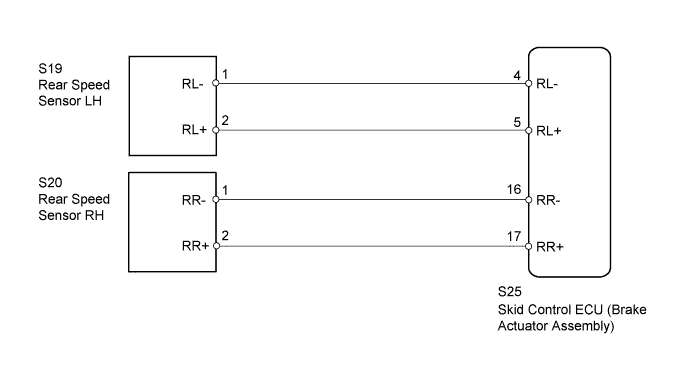
WIRING DIAGRAM
INSPECTION PROCEDURE
CHECK HARNESS AND CONNECTOR (MOMENTARY INTERRUPTION)
READ VALUE USING INTELLIGENT TESTER (RR/RL WHEEL SPEED)
RECONFIRM DTC
CHECK HARNESS AND CONNECTOR (SKID CONTROL ECU - REAR SPEED SENSOR)
CHECK TERMINAL VOLTAGE (SENSOR POWER SUPPLY VOLTAGE TERMINAL)
DTC C1407 Open or Short in Rear Speed Sensor RH Circuit |
DTC C1408 Open or Short in Rear Speed Sensor LH Circuit |
DESCRIPTION
Refer to DTCs C1401 and C1402 (Toyota Fortuner RM000000XI90JJX.html).DTC Code
| DTC Detection Condition
| Trouble Area
|
C1407
C1408
| Either condition is met:
- An open in the speed sensor signal circuit continues for 0.5 seconds or more.
- With the IG1 terminal voltage at 9.5 V or higher, the sensor power supply voltage decreases for 0.5 seconds or more.
| - Rear speed sensor RH/LH
- Speed sensor circuit
- Skid control ECU (Brake actuator assembly)
|
- HINT:
- DTC C1407 is for the rear speed sensor RH.
- DTC C1408 is for the rear speed sensor LH.
WIRING DIAGRAM
INSPECTION PROCEDURE
- NOTICE:
- After replacing the brake actuator assembly, perform calibration (Toyota Fortuner RM000000XHR06WX.html).
- Check the speed sensor signal after replacement (Toyota Fortuner RM000000XHT08TX.html).
- Before disconnecting the connector, make sure that there are no problems with the connection.
- After disconnecting the connector, make sure that the connector case and terminals are not deformed or corroded.
| 1.CHECK HARNESS AND CONNECTOR (MOMENTARY INTERRUPTION) |
Using the intelligent tester, check for any momentary interruption in the wire harness and connector corresponding to the DTC (Toyota Fortuner RM000000XHS0A8X.html).
ABS/VSC/TRCTester Display
| Measurement Item/Range
| Normal Condition
| Diagnostic Note
|
RR Speed Open
| Rear speed sensor RH open circuit detection / Error or Normal
| Normal
| -
|
RL Speed Open
| Rear speed sensor LH open circuit detection / Error or Normal
| Normal
| -
|
- OK:
- Normal (there are no momentary interruptions).
- HINT:
- Perform the above inspection before removing the sensor or disconnecting a connector.
| 2.READ VALUE USING INTELLIGENT TESTER (RR/RL WHEEL SPEED) |
Turn the ignition switch off.
Connect the intelligent tester to the DLC3.
Start the engine.
Turn the intelligent tester on.
Enter the following menus: Chassis / ABS/VSC/TRC / Data List, and then drive the vehicle.
ABS/VSC/TRCTester Display
| Measurement Item/Range
| Normal Condition
| Diagnostic Note
|
RR Wheel Speed
| Rear speed sensor RH reading / Min.: 0 km/h (0 mph), Max.: 326 km/h (202 mph)
| Actual wheel speed
| No large fluctuations when driving at a constant speed.
|
RL Wheel Speed
| Rear speed sensor LH reading / Min.: 0 km/h (0 mph), Max.: 326 km/h (202 mph)
| Actual wheel speed
| No large fluctuations when driving at a constant speed.
|
Check the speed value output from the speed sensor displayed on the intelligent tester.
- HINT:
- Factors that affect the indicated vehicle speed include tire size, tire inflation and tire wear. The speed indicated on the speedometer has an allowable margin of error. This can be tested using a speedometer tester (calibrated chassis dynamometer). For details about testing and the margin of error, refer to the reference chart (Toyota Fortuner RM0000011JB00WX.html).
- OK:
- The speed value output from the speed sensor displayed on the intelligent tester is the same as the actual vehicle speed measured using a speedometer tester (calibrated chassis dynamometer).
Clear the DTC (Toyota Fortuner RM000000XHV0C7X.html).
Turn the ignition switch off.
Start the engine.
Drive the vehicle at a speed of 40 km/h (25 mph) or more for at least 60 seconds.
Check if the same DTC is output (Toyota Fortuner RM000000XHV0C7X.html).
ResultResult
| Proceed to
|
DTC is not output
| A
|
DTC is output
| B
|
- HINT:
- If troubleshooting has been carried out according to Problem Symptoms Table, refer back to the table and proceed to the next suspected area (Toyota Fortuner RM000000XHN0BDX.html).
| 4.CHECK HARNESS AND CONNECTOR (SKID CONTROL ECU - REAR SPEED SENSOR) |
Turn the ignition switch off.
Disconnect the skid control ECU (brake actuator assembly) connector.
Disconnect the rear speed sensor connector.
Measure the resistance according to the value(s) in the table below.
- Standard Resistance:
for RHTester Connection
| Condition
| Specified Condition
|
S25-17 (RR+) - S20-2 (RR+)
| Always
| Below 1 Ω
|
S25-17 (RR+) - Body ground
| Always
| 10 kΩ or higher
|
S25-16 (RR-) - S20-1 (RR-)
| Always
| Below 1 Ω
|
S25-16 (RR-) - Body ground
| Always
| 10 kΩ or higher
|
for LHTester Connection
| Condition
| Specified Condition
|
S25-5 (RL+) - S19-2 (RL+)
| Always
| Below 1 Ω
|
S25-5 (RL+) - Body ground
| Always
| 10 kΩ or higher
|
S25-4 (RL-) - S19-1 (RL-)
| Always
| Below 1 Ω
|
S25-4 (RL-) - Body ground
| Always
| 10 kΩ or higher
|
| | REPAIR OR REPLACE HARNESS OR CONNECTOR |
|
|
| 5.CHECK TERMINAL VOLTAGE (SENSOR POWER SUPPLY VOLTAGE TERMINAL) |
Turn the ignition switch off.
Connect the skid control ECU (brake actuator assembly) connector.
Disconnect the rear speed sensor connector.
Measure the voltage according to the value(s) in the table below.
- Standard Voltage:
for RHTester Connection
| Switch Condition
| Specified Condition
|
S20-2 (RR+) - Body ground
| Ignition switch ON
| 8 to 14 V
|
for LHTester Connection
| Switch Condition
| Specified Condition
|
S19-2 (RL+) - Body ground
| Ignition switch ON
| 8 to 14 V
|
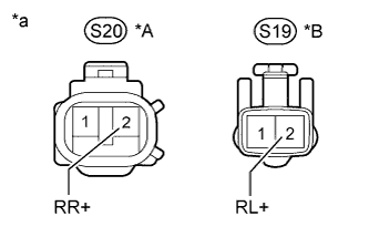
Text in Illustration*A
| for RH
|
*B
| for LH
|
*a
| Front view of wire harness connector
(to Rear Speed Sensor)
|