Can Communication System (W/ Vsc) Skid Control Ecu Communication Stop Mode
DESCRIPTION
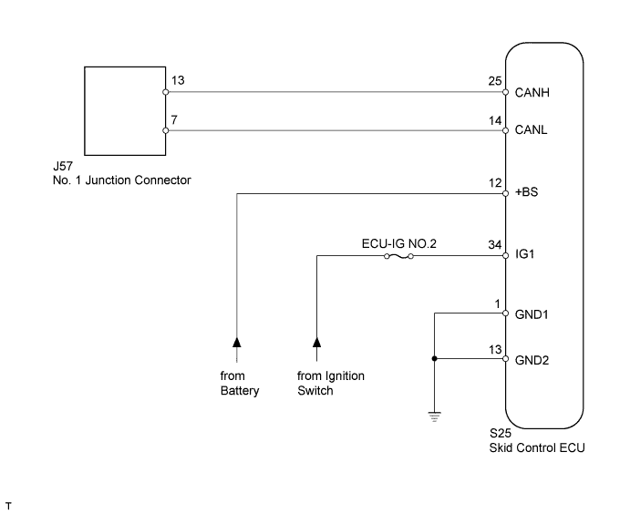
WIRING DIAGRAM
INSPECTION PROCEDURE
DISCONNECT CABLE FROM NEGATIVE BATTERY TERMINAL
CHECK FOR OPEN IN CAN BUS WIRE (SKID CONTROL ECU BRANCH WIRE)
CHECK HARNESS AND CONNECTOR (SKID CONTROL ECU - BATTERY AND BODY GROUND)
CAN COMMUNICATION SYSTEM (w/ VSC) - Skid Control ECU Communication Stop Mode |
DESCRIPTION
Detection Item
| Symptom
| Trouble Area
|
Skid Control ECU Communication Stop Mode
| When either condition below is met:
- Skid Control (ABS/VSC/TRAC) is not displayed on "Bus Check".
- "Skid Control ECU Communication Stop Mode" in "DTC Combination Table" applies.
| - Power source or inside skid control ECU
- Skid control ECU branch wire or connector
- Brake actuator assembly (skid control ECU)
|
WIRING DIAGRAM
INSPECTION PROCEDURE
- HINT:
- Operating the ignition switch, any switches or any doors triggers related ECU and sensor communication with the CAN, which causes resistance variation.
| 1.DISCONNECT CABLE FROM NEGATIVE BATTERY TERMINAL |
Disconnect the cable from the negative (-) battery terminal before measuring the resistances of the main wire and the branch wire.
- CAUTION:
- For vehicles with SRS:
- Wait at least 90 seconds after disconnecting the cable from the negative (-) battery terminal to disable the SRS system.
- NOTICE:
- When disconnecting the cable from the negative (-) battery terminal, some systems need to be initialized after the cable is reconnected (Toyota Fortuner RM000004W63000X.html).
| 2.CHECK FOR OPEN IN CAN BUS WIRE (SKID CONTROL ECU BRANCH WIRE) |
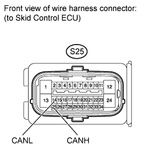
Disconnect the S25 skid control ECU connector.
Measure the resistance according to the value(s) in the table below.
- Standard Resistance:
Tester Connection
| Switch Condition
| Specified Condition
|
S25-25 (CANH) - S25-14 (CANL)
| Ignition switch off
| 54 to 69 Ω
|
| | REPAIR OR REPLACE SKID CONTROL ECU BRANCH WIRE OR CONNECTOR (CANH, CANL) |
|
|
| 3.CHECK HARNESS AND CONNECTOR (SKID CONTROL ECU - BATTERY AND BODY GROUND) |
Reconnect the cable to the negative (-) battery terminal.
- NOTICE:
- When disconnecting the cable from the negative (-) battery terminal, some systems need to be initialized after the cable is reconnected (Toyota Fortuner RM000004W63000X.html).
Measure the resistance according to the value(s) in the table below.
- Standard Resistance:
Tester Connection
| Condition
| Specified Condition
|
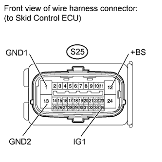
S25-1 (GND1) - Body ground
| Always
| Below 1 Ω
|
S25-13 (GND2) - Body ground
| Always
| Below 1 Ω
|
Measure the voltage according to the value(s) in the table below.
- Standard Voltage:
Tester Connection
| Switch Condition
| Specified Condition
|
S25-12 (+BS) - Body ground
| Always
| 11 to 14 V
|
S25-34 (IG1) - Body ground
| Ignition switch ON
| 11 to 14 V
|
| | REPAIR OR REPLACE HARNESS OR CONNECTOR |
|
|