Dtc P2563 Turbocharger/Supercharger Boost Control Position Sensor A Circuit Range/Performance
DESCRIPTION
WIRING DIAGRAM
INSPECTION PROCEDURE
CHECK OTHER DTC OUTPUT (IN ADDITION TO DTC P2563)
CHECK HARNESS AND CONNECTOR (NOZZLE VANE POSITION SENSOR - TURBO MOTOR DRIVER)
INSPECT TURBO MOTOR DRIVER
INSPECT NOZZLE VANE POSITION SENSOR
REPLACE TURBO MOTOR DRIVER
CHECK WHETHER DTC OUTPUT RECURS (P2564, P2565, P2588 AND/OR P2589)
DTC P2563 Turbocharger/Supercharger Boost Control Position Sensor "A" Circuit Range/Performance |
DTC P2564 Turbocharger/Supercharger Boost Control Position Sensor "A" Circuit Low |
DTC P2565 Turbocharger/Supercharger Boost Control Position Sensor "A" Circuit High |
DTC P2588 Turbocharger/Supercharger Boost Control Position Sensor "B" Circuit Low |
DTC P2589 Turbocharger/Supercharger Boost Control Position Sensor "B" Circuit High |
DESCRIPTION
Variable nozzle vane type turbocharger consists primarily of a compressor wheel, turbine wheel, nozzle vane, unison ring, DC motor and nozzle vane position sensor.The nozzle vane position sensor consists of a Hall IC and a magnetic yoke that rotates in unison with the movement of the linkage that actuates the nozzle vane. The nozzle vane position sensor converts the changes in the magnetic flux that are caused by the rotation of the DC motor (hence, the rotation of the magnetic yoke) into electric signals, and outputs them to the turbo motor driver. The turbo motor driver determines the actual nozzle vane position from the electric signals in order to calculate the target nozzle vane position.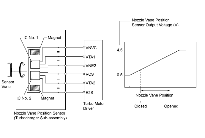
DTC No.
| DTC Detection Condition
| Trouble Area
|
P2563
| Difference between VTA1 and VTA2 0.8 V or more for 0.5 seconds or more
(1 trip detection logic)
| Nozzle vane position sensor (Turbocharger sub-assembly)
|
P2564
| VTA1 0.5 V or less for 0.5 seconds or more
(1 trip detection logic)
| - Nozzle vane position sensor (Turbocharger sub-assembly)
- Open or short in nozzle vane position sensor circuit
- Turbo motor driver
|
P2565
| VTA1 4.5 V or more for 0.5 seconds or more
(1 trip detection logic)
| - Nozzle vane position sensor (Turbocharger sub-assembly)
- Open or short in nozzle vane position sensor circuit
- Turbo motor driver
|
P2588
| VTA2 0.5 V or less for 0.5 seconds or more
(1 trip detection logic)
| - Nozzle vane position sensor (Turbocharger sub-assembly)
- Open or short in nozzle vane position sensor circuit
- Turbo motor driver
|
P2589
| VTA2 4.5 V or more for 0.5 seconds or more
(1 trip detection logic)
| - Nozzle vane position sensor (Turbocharger sub-assembly)
- Open or short in nozzle vane position sensor circuit
- Turbo motor driver
|
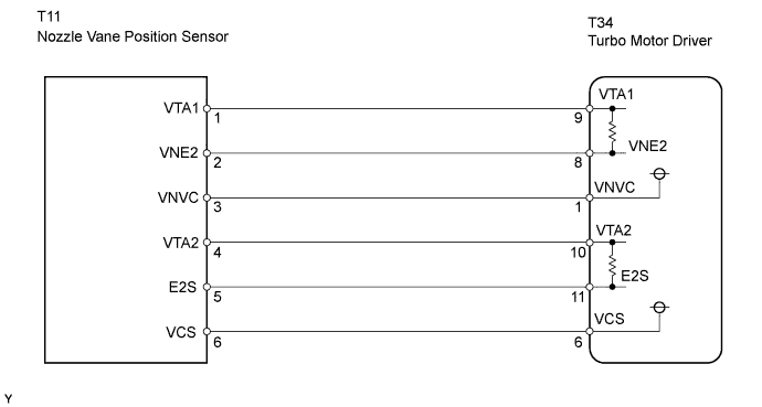
WIRING DIAGRAM
INSPECTION PROCEDURE
- NOTICE:
- After replacing the ECM, the new ECM needs registration (Toyota Fortuner RM0000012XK04BX.html) and initialization (Toyota Fortuner RM000000TIN04NX.html).
- HINT:
- Read freeze frame data using the intelligent tester. Freeze frame data records the engine conditions when a malfunction is detected. When troubleshooting, freeze frame data can help determine if the vehicle was moving or stationary, if the engine was warmed up or not, and other data from the time the malfunction occurred.
| 1.CHECK OTHER DTC OUTPUT (IN ADDITION TO DTC P2563) |
Connect the intelligent tester to the DLC3.
Turn the ignition switch ON and turn the tester ON.
Enter the following menus: Powertrain / Engine and ECT / DTC.
Read the DTCs.
- Result:
Display (DTC Output)
| Proceed to
|
P2563, P2564, P2565, P2588 and/or P2589
| A
|
P2563, P2564, P2565, P2588 and/or P2589, and other DTCs
| B
|
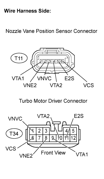
| 2.CHECK HARNESS AND CONNECTOR (NOZZLE VANE POSITION SENSOR - TURBO MOTOR DRIVER) |
Disconnect the T11 nozzle vane position sensor connector.
Disconnect the T34 turbo motor driver connector.
Measure the resistance of the wire harness side connectors.
- Standard resistance (Check for open):
Tester Connection
| Specified Condition
|
VTA1 (T11-1) - VTA1 (T34-9)
| Below 1 Ω
|
VNE2 (T11-2) - VNE2 (T34-8)
| Below 1 Ω
|
VNVC (T11-3) - VNVC (T34-1)
| Below 1 Ω
|
VTA2 (T11-4) - VTA2 (T34-10)
| Below 1 Ω
|
E2S (T11-5) - E2S (T34-11)
| Below 1 Ω
|
VCS (T11-6) - VCS (T34-6)
| Below 1 Ω
|
- Standard resistance (Check for short):
Tester Connection
| Specified Condition
|
VTA1 (T11-1) or VTA1 (T34-9) - Body ground
| 10 kΩ or higher
|
VNE2 (T11-2) or VNE2 (T34-8) - Body ground
| 10 kΩ or higher
|
VNVC (T11-3) or VNVC (T34-1) - Body ground
| 10 kΩ or higher
|
VTA2 (T11-4) or VTA2 (T34-10) - Body ground
| 10 kΩ or higher
|
E2S (T11-5) or E2S (T34-11) - Body ground
| 10 kΩ or higher
|
VCS (T11-6) or VCS (T34-6) - Body ground
| 10 kΩ or higher
|
| | REPAIR OR REPLACE HARNESS OR CONNECTOR |
|
|
| 3.INSPECT TURBO MOTOR DRIVER |
Disconnect the T11 nozzle vane position sensor connector.
Turn the ignition switch ON.
Measure the voltage between the terminals of the nozzle vane position sensor connector.
- Standard voltage:
Tester Connection
| Specified Condition
|
VNVC (T11-3) - VNE2 (T11-2)
| 4.5 to 5.5 V
|
VCS (T11-6) - E2S (T11-5)
| 4.5 to 5.5 V
|
| | REPLACE TURBO MOTOR DRIVER |
|
|
| 4.INSPECT NOZZLE VANE POSITION SENSOR |
Turn the ignition switch ON (IG).
Measure the voltage between the terminals of the turbo motor driver connector.
- Standard voltage:
Tester Connection
| Specified Condition
|
VTA1 (T34-9) - VNE2 (T34-8)
| 0.5 to 4.5 V
|
VTA2 (T34-10) - E2S (T34-11)
| 0.5 to 4.5 V
|
Check the difference between the voltage values.
- Result:
- Voltage difference between VTA1 and VTA2 is within 0.8 V
| 5.REPLACE TURBO MOTOR DRIVER |
| 6.CHECK WHETHER DTC OUTPUT RECURS (P2564, P2565, P2588 AND/OR P2589) |
Connect the intelligent tester to the DLC3.
Turn the ignition switch ON and turn the tester ON.
Clear DTCs (Toyota Fortuner RM0000012WY00RX.html).
Start the engine.
Perform the test drive.
Enter the following menus: Powertrain / Engine and ECT / DTC.
Read the DTCs.
- Result:
Display (DTC output)
| Proceed to
|
P2563, P2564, P2565, P2588 and/or P2589 is output again
| A
|
No output
| B
|