Air Conditioning System (For Automatic Air Conditioning System) -- Terminals Of Ecu |
| CHECK AIR CONDITIONING AMPLIFIER ASSEMBLY |

Disconnect the A38 air conditioning amplifier assembly connector.
Measure the voltage and resistance according to the value(s) in the table below.
Terminal No. (Symbol) Wiring Color Terminal Description Condition Specified Condition A38-1 (GND) - Body ground L - Body ground Ground Always Below 1 Ω A38-5 (+B1) - A38-1 (GND) L-Y - L Battery power source Always 11 to 14 V A38-6 (IG+) - A38-1 (GND) R-L - L IG power source Ignition switch off Below 1 V Ignition switch ON 11 to 14 V A38-13 (MGC) - Body ground B - Body ground Magnet clutch signal Ignition switch ON 11 to 14 V Ignition switch off Below 1 V A38-14 (HR) - Body ground L-W - Body ground No. 1 heater relay signal Ignition switch ON 11 to 14 V Ignition switch off Below 1 V - If the result is not as specified, there may be a malfunction on the wire harness side.
- If the result is not as specified, there may be a malfunction on the wire harness side.
Reconnect the A38 air conditioning amplifier assembly connector.
Measure the voltage and resistance according to the value(s) in the table below.
Terminal No. (Symbol) Wiring Color Terminal Description Condition Specified Condition A38-2 (BLW) - Body ground L-B - Body ground Blower motor speed control voltage - Ignition switch ON
- Blower switch on (LO level)
Pulse generation
(See waveform 1)A38-3 (AOF) - A38-1 (GND) Y-B - L Mode damper servo operation voltage - Ignition switch ON
- Blower switch on (LO level)
- Mode switch DEF
Below 1 V - Ignition switch ON
- Blower switch on (LO level)
- Mode switch FACE
11 to 14 V A38-4 (AOD) - A38-1 (GND) R-B - L Mode damper servo operation voltage - Ignition switch ON
- Blower switch on (LO level)
- Mode switch FACE
Below 1 V - Ignition switch ON
- Blower switch on (LO level)
- Mode switch DEF
11 to 14 V A38-7 (ACT) - A38-1 (GND) R-L - L Magnet clutch on permit input signal - Engine idling
- Blower switch on (LO level)
- A/C switch off or on (magnet clutch off)
Below 1 V - Engine idling
- Blower switch on (LO level)
- A/C switch on (magnet clutch on)
11 to 14 V A38-8 (TW) - A38-1 (GND) P - L Engine coolant temperature sensor signal Ignition switch ON Pulse generation A38-9 (SPD) - Body ground V-W - Body ground Vehicle speed signal Driving at approximately 20 km/h (12 mph) Pulse generation
(See waveform 2)A38-13 (MGC) - Body ground B - Body ground Magnet clutch signal - Engine idling
- A/C switch on (magnet clutch on permitted)
Below 1 V - Engine idling
- A/C switch off or on (magnet clutch on not permitted)
11 to 14 V A38-17 (AMH) - A38-1 (GND) L - L Air mix damper servo operation signal - Ignition switch ON
- Blower switch on (LO level)
- Temperature switch MAX HOT
11 to 14 V - Ignition switch ON
- Blower switch on (LO level)
- Temperature switch MAX COLD
Below 1 V A38-18 (TAMO) - A38-1 (GND) P - L Ambient temperature signal Ignition switch ON Pulse generation A38-19 (AMC) - A38-1 (GND) R-W - L Air mix damper servo operation signal - Ignition switch ON
- Blower switch on (LO level)
- Temperature switch MAX HOT
Below 1 V - Ignition switch ON
- Blower switch on (LO level)
- Temperature switch MAX COLD
11 to 14 V A38-21 (AC1) - A38-1 (GND) Y - L Idle-up request signal - Engine idling
- Blower switch on (LO level)
- A/C switch off
11 to 14 V - Engine idling
- Blower switch on (LO level)
- A/C switch on
Below 1 V A38-22 (AIR) - A38-1 (GND) L-W - L Recirculation damper servo operation voltage - Ignition switch ON
- Blower switch on (LO level)
- Fresh switch on
Below 1 V - Ignition switch ON
- Blower switch on (LO level)
- Recirculation switch on
11 to 14 V A38-23 (AIF) - A38-1 (GND) G-Y - L Recirculation damper servo operation voltage - Ignition switch ON
- Blower switch on (LO level)
- Recirculation switch on
Below 1 V - Ignition switch ON
- Blower switch on (LO level)
- Fresh switch on
11 to 14 V A37-1 (TE) - A37-14 (SG-4) G - P No. 1 cooler thermistor signal - Ignition switch ON
- Evaporator temperature 0°C (32°F)
2.0 to 2.4 V - Ignition switch ON
- Evaporator temperature 15°C (59°F)
1.4 to 1.8 V A37-2 (S5-3) - A38-1 (GND) W-R - L Power supply for solar sensor Ignition switch ON 4.5 to 5.5 V A37-5 (PSW) - A38-1 (GND) Y-B - L Air conditioner pressure sensor signal - Engine idling
- Refrigerant pressure normal
Below 1 V - Engine idling
- Refrigerant pressure less than 0.196 MPa (2.0 kgf/cm2, 28 psi) or more than 3.14 MPa (32.0 kgf/cm2, 455 psi)
11 to 14 V A37-7 (TS) - A37-2 (S5-3) L-W - W-R Solar sensor signal - Ignition switch ON
- Solar sensor subjected to electric light
- Vehicle indoors
0.8 to 4.3 V - Ignition switch ON
- Solar sensor covered with cloth
- Vehicle indoors
Below 0.8 V A37-11 (SG-2) - Body ground L-Y - Body ground Ground for pulse position sensor (Mode damper servo) Always Below 1 Ω A37-13 (SG-3) - Body ground BR-Y - Body ground Ground for cooler thermistor Always Below 1 Ω A37-14 (SG-4) - Body ground P - Body ground Ground for No. 1 cooler thermistor Always Below 1 Ω A37-16 (AGND) - A37-21 (AUXO) R-L - LG-R Input signal for pulse position sensor (recirculation damper servo) - Ignition switch ON
- Blower switch on (LO level)
- Air inlet control recirculation to fresh or vice versa
Pulse generation A37-17 (PIA) - A37-21 (AUXO) P-B - LG-R Input signal for pulse position sensor (recirculation damper servo) - Ignition switch ON
- Blower switch on (LO level)
- Air inlet control recirculation to fresh or vice versa
Pulse generation A37-18 (TR) - A37-13 (SG-3) GR - BR-Y Cooler thermistor signal - Ignition switch ON
- Cabin temperature 25°C (77°F)
1.8 to 2.2 V - Ignition switch ON
- Cabin temperature 40°C (104°F)
1.2 to 1.6 V A37-20 (SG-1) - Body ground BR-Y - Body ground Ground for pulse position sensor (air mix damper servo) Always Below 1 V A37-21 (AUXO) - Body ground LG-R - Body ground Ground for pulse position sensor (recirculation damper servo) Always Below 1 Ω A37-23 (PMB) - A37-20 (SG-1) W-L - BR-Y Input signal for pulse position sensor (air mix damper servo) - Ignition switch ON
- Blower switch on (LO level)
- Temperature switch MAX HOT to MAX COLD
Pulse generation A37-24 (PMA) - A37-20 (SG-1) W-R - BR-Y Input signal for pulse position sensor (air mix damper servo) - Ignition switch ON
- Blower switch on (LO level)
- Temperature switch MAX COLD to MAX HOT
Pulse generation A37-25 (POB) - A37-11(SG-2 ) LG - L-Y Input signal for pulse position sensor (mode damper servo) - Ignition switch ON
- Blower switch on (LO level)
- Mode control FACE to DEF or vice versa
Pulse generation A37-26 (POA) - A37-11 (SG-2) L-O - L-Y Input signal for pulse position sensor (mode damper servo) - Ignition switch ON
- Blower switch on (LO level)
- Mode control FACE to DEF or vice versa
Pulse generation - If the result is not as specified, the air conditioning amplifier assembly may have a malfunction.
- Ignition switch ON
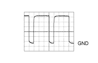
Using an oscilloscope, check waveform 1.
Blower motor control signal Item Content Terminal No. (Symbol) A38-2 (BLW) - Body ground Tool Setting 1 V/DIV., 50 μsec./DIV. Condition Ignition switch ON, Blower switch on (LO level) - HINT:
- When the blower level is increased, the duty ratio changes accordingly.
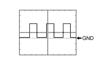
Using an oscilloscope, check waveform 2.
Vehicle speed signal Item Content Terminal No. (Symbol) A38-9 (SPD) - Body ground Tool Setting 5 V/DIV., 20 ms./DIV. Condition Driving at approximately 20 km/h (12 mph) - HINT:
- As the vehicle speed increases, the wavelength becomes shorter.
 |
 |
| CHECK ECM (for 1KD-FTV) |
Measure the voltage according to the value(s) in the table below.
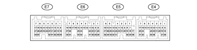
If the result is not as specified, the ECM may have a malfunction.Terminal No. (Symbol) Wiring Color Terminal Description Condition Specified Condition E4-2 (THWO) - E6-7 (E1) P - BR Engine coolant temperature output signal Engine idling Pulse generation E5-18 (AC1) - E6-7 (E1) Y - BR Idle-up request signal - Engine idling
- Blower switch on (LO level)
- A/C switch on
Below 1 V - Engine idling
- Blower switch on (LO level)
- A/C switch off
11 to 14 V E5-19 (ACT) - E6-7 (E1) R-L - BR Magnet clutch on permit output signal - Engine idling
- Blower switch on (LO level)
- A/C switch off or on (magnet clutch on)
Below 1 V - Engine idling
- Blower switch on (LO level)
- A/C switch on (magnet clutch on)
11 to 14 V - Engine idling
| CHECK ECM (for 1GR-FE) |

Measure the voltage according to the value(s) in the table below.
If the result is not as specified, the ECM may have a malfunction.Terminal No. (Symbol) Wiring Color Terminal Description Condition Specified Condition E13-14 (THWO) - E17-1 (E1) P - BR Engine coolant temperature output signal Engine idling Pulse generation E13-24 (AC1) - E17-1 (E1) Y - BR Idle-up request signal - Engine idling
- Blower switch on (LO level)
- A/C switch on
Below 1 V - Engine idling
- Blower switch on (LO level)
- A/C switch off
11 to 14 V E13-25 (ACT) - E17-1 (E1) R-L - BR Magnet clutch on permit output signal - Engine idling
- Blower switch on (LO level)
- A/C switch off or on (magnet clutch on)
Below 1 V - Engine idling
- Blower switch on (LO level)
- A/C switch on (magnet clutch on)
11 to 14 V - Engine idling
| CHECK ACCESSORY METER ASSEMBLY |

Measure the voltage according to the value(s) in the table below.
Terminal No. (Symbol) Wiring Color Terminal Description Condition Specified Condition A43-3 (TH+) - A43-2 (SG) W-G - BR-Y Ambient temperature sensor signal - Ignition switch ON
- Ambient temperature 20 to 30°C (68 to 86°F)
1.0 to 1.6 V Ambient temperature sensor signal - Ignition switch ON
- Ambient temperature 30 to 50°C (86 to 122°F)
0.6 to 1.0 V A43-9 (DATA) - A43-1 (GND1) P - LG Ambient temperature sensor signal Ignition switch ON Pulse generation - If the result is not as specified, the accessory meter assembly may have a malfunction.
- Ignition switch ON
| CHECK COMBINATION METER ASSEMBLY |

Measure the voltage according to the value(s) in the table below.
Terminal No. (Symbol) Wiring Color Terminal Description Condition Specified Condition C27-6 - C27-22 V-R - Y Vehicle speed signal Driving at approximately 20 km/h (12 mph) Pulse generation
(See waveform)- If the result is not as specified, the combination meter assembly may have a malfunction.
- If the result is not as specified, the combination meter assembly may have a malfunction.
Using an oscilloscope, check waveform 1.
Vehicle speed signal Item Content Terminal No. (Symbol) C27-6 - C27-22 Tool Setting 5 V/DIV., 20 ms./DIV. Condition Driving at approximately 20 km/h (12 mph) - HINT:
- As the vehicle speed is increased. the wavelength becomes shorter.
|