Air Conditioning System (For Manual Air Conditioning System) -- Terminals Of Ecu |
| CHECK AIR CONDITIONING AMPLIFIER ASSEMBLY |
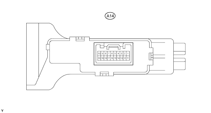
Disconnect the A14 amplifier connector.
Measure the voltage and resistance of the wire harness side connector.
Symbols (Terminal No.) Wiring Color Terminal Description Condition Specified Condition IG+ (A14-10) - GND (A14-18) R-L - L Power source (IG) Ignition switch OFF Below 1 V IG+ (A14-10) - GND (A14-18) R-L - L Power source (IG) Ignition switch ON 10 to 14 V GND (A14-18) - Body ground L - Body ground Ground Always Below 1 Ω ACON (A14-4) - GND (A14-18) R-G - L A/C switch signal Ignition switch START
Blower switch ON
A/C switch OFFBelow 1 V ACON (A14-4) - GND (A14-18) R-G - L A/C switch signal Ignition switch START
Blower switch ON
A/C switch ON10 to 14 V IND- (A14-13) - GND (A14-18) R-L - L A/C indicator light signal Ignition switch START
Blower switch ON
A/C switch OFFBelow 1 V IND- (A14-13) - GND (A14-18) R-L - L A/C indicator light signal Ignition switch START
Blower switch ON
A/C switch ON10 to 14 V - If the result is not as specified, there may be a malfunction on the wire harness side.
- If the result is not as specified, there may be a malfunction on the wire harness side.
Reconnect the A14 amplifier connector.
Measure the voltage and resistance of the connector.
Symbols (Terminal No.) Wiring Color Terminal Description Condition Specified Condition PSW (A14-3) - GND (A14-18) Y-B - L A/C pressure switch signal Ignition switch START
Refrigerant pressure normal: 0.18 MPa (1.9 kgf/cm2, 26 psi) to 3.03 MPa (31.0 kgf/cm2, 440 psi)
A/C switch ON
Blower switch ON10 to 14 V PSW (A14-3) - GND (A14-18) Y-B - L A/C pressure switch signal Ignition switch START
Refrigerant pressure less than: 0.18 MPa (1.9 kgf/cm2, 26 psi) or more than 3.03 MPa (31.0 kgf/cm2, 440 psi)
A/C switch ON
Blower switch ONBelow 1 V TE (A14-7) - SG-1 (A14-8) G - P A/C evaporator temperature sensor signal Ignition switch ON
Evaporator temperature is 0°C (32°F)
Temperature control knob: MAX COOL2.0 to 2.4 V TE (A14-7) - SG-1 (A14-8) G - P A/C evaporator temperature sensor signal Ignition switch ON
Evaporator temperature is 15°C (59°F)
Temperature control knob: MAX COOL1.4 to 1.8 V SG1-1 (A14-8) - Body ground P-L Ground for A/C evaporator temperature sensor Always Below 1 Ω MGC (A14-1) - GND (A14-18) L-W - L Magnet clutch signal Ignition switch START
Magnet clutch is not engagedBelow 1 V MGC (A14-1) - GND (A14-18) L-W - L Magnet clutch signal Ignition switch START
Magnet clutch is engaged10 to 14 V ACT (A14-2) - GND (A14-18) R-L - L Magnet on permit signal Ignition switch START
A/C switch OFF
Blower switch ONBelow 1 V ACT (A14-2) - GND (A14-18) R-L - L Magnet on permit signal Ignition switch START
A/C switch ON
Blower switch ON10 to 14 V AC1 (A14-14) - GND (A14-18) Y - L Idle-up request signal Ignition switch START
Magnet clutch is not engaged10 to 14 V AC1 (A14-14) - GND (A14-18) Y - L Idle-up request signal Ignition switch START
Magnet clutch is engagedBelow 1 V - If the result is not specified, the A/C amplifier may have a malfunction.
- If the result is not specified, the A/C amplifier may have a malfunction.