Dtc 18 (5) Spill Control Circuit Malfunction
DESCRIPTION
WIRING DIAGRAM
INSPECTION PROCEDURE
INSPECT SPILL CONTROL VALVE
CHECK ECM (SPV+ VOLTAGE)
CHECK ECM (SPV- VOLTAGE)
CHECK HARNESS AND CONNECTOR (ECM - SPILL CONTROL VALVE)
DTC 18 (5) Spill Control Circuit Malfunction |
DESCRIPTION
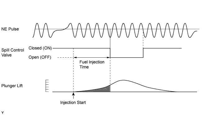
The ECM operates the spill control valve to control fuel injection volume. The spill control valve is mounted on the injection pump. The spill control valve's solenoid valve opens and closes the injection pressure release port. During fuel injection , the spill control valve is ON (closed). The ECM determines the basic fuel injection amount based on the engine speed and acceleration pedal opening angle. Then the ECM uses several other correctional factors to determine the final fuel injection amount. After fuel injection has begun, the ECM ensures the final fuel injection amount by performing the following: 1) by counting the number of NE signals, and 2) by operating the spill control valve from ON (close) to OFF (open) (injection pressure release port is open).DTC No.
| DTC Detection Condition
| Trouble Area
|
18 (5)
| Open or short in spill control valve at 500 rpm or more
| - Open or short in spill control valve circuit
- Spill control valve
- ECM
|
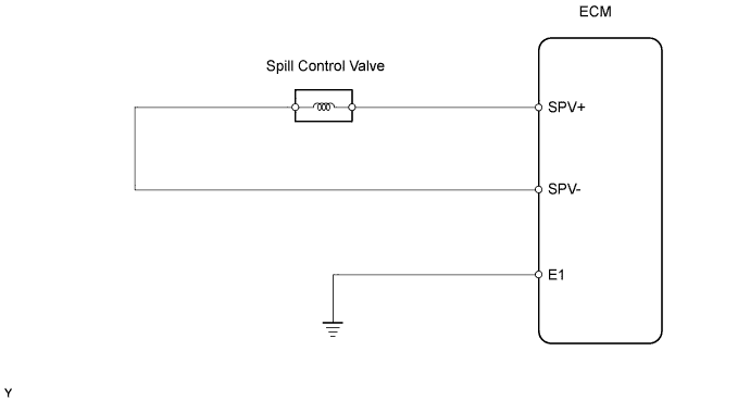
WIRING DIAGRAM
INSPECTION PROCEDURE
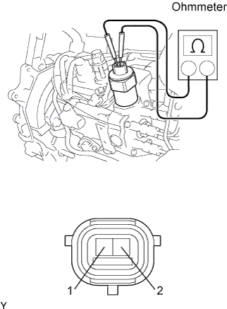
| 1.INSPECT SPILL CONTROL VALVE |
Disconnect the S24 spill control valve connector.
Measure the resistance of the spill control valve.
- Standard resistance:
Tester Connection
| Condition
| Specified Condition
|
1 - 2
| 20°C (68°F)
| 1 to 2 Ω
|
- HINT:
- The spill control valve is integrated with the injection pump. If the spill control valve needs to be replaced, the entire injection pump must be replaced.
| | REPLACE INJECTION PUMP ASSEMBLY |
|
|
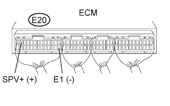
| 2.CHECK ECM (SPV+ VOLTAGE) |
Disconnect the S24 spill control valve connector.
Turn the ignition switch ON.
Measure the voltage of the ECM connector.
- Standard voltage:
Tester Connection
| Specified Condition
|
E20-12 (SPV+) - E20-14 (E1)
| 9 to 14 V
|
| 3.CHECK ECM (SPV- VOLTAGE) |
Turn the ignition switch ON.
Measure the voltage of the ECM connector.
- Standard voltage:
Tester Connection
| Specified Condition
|
E20-25 (SPV-) - E20-14 (E1)
| 9 to 14 V
|
Tool Setting
| Condition
|
20 V/DIV., 10 msec./DIV.
| During idling
|
While idling, measure the waveform with an oscilloscope connected between the specified terminals of ECM connector.
- OK:
Tester Connection
| Specified Condition
|
E20-25 (SPV-) - E20-14 (E1)
| Correct waveform is as shown
|
| | CHECK FOR INTERMITTENT PROBLEMS |
|
|
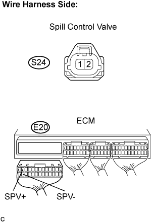
| 4.CHECK HARNESS AND CONNECTOR (ECM - SPILL CONTROL VALVE) |
Disconnect the S24 spill control valve connector.
Disconnect the E20 ECM connector.
Measure the resistance of the wire harness side connectors.
- Standard resistance:
Tester Connection
| Specified Condition
|
S24-2 - E20-12 (SPV+)
| Below 1 Ω
|
S24-1 - E20-25 (SPV-)
| Below 1 Ω
|
S24-2 or E20-12 (SPV+) - Body ground
| 10 kΩ or higher
|
S24-1 or E20-25 (SPV-) - Body ground
| 10 kΩ or higher
|
| | REPAIR OR REPLACE HARNESS OR CONNECTOR |
|
|