Dtc 14 (4) Timing Control System Malfunction
DESCRIPTION
WIRING DIAGRAM
INSPECTION PROCEDURE
INSPECT TIMING CONTROL VALVE
CHECK ECM (TCV VOLTAGE)
CHECK ECM (TCV VOLTAGE, SIGNAL)
CHECK FUEL FILTER
CHECK FUEL LEAK
CHECK TIMING CONTROL VALVE (POWER SOURCE)
CHECK HARNESS AND CONNECTOR (ECM - INTEGRATION RELAY [MAIN RELAY])
DTC 14 (4) Timing Control System Malfunction |
DESCRIPTION
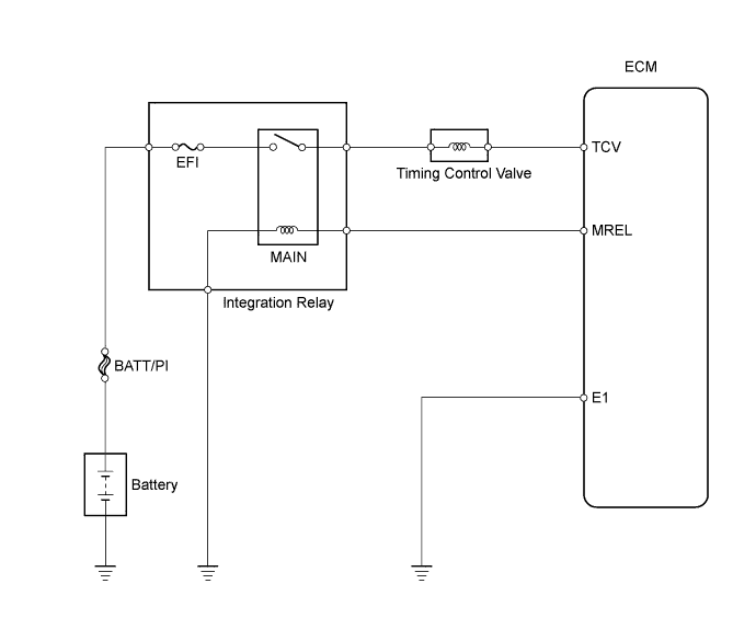
The ECM controls the injection timing by actuating the timing control valve. The timing control valve is mounted on the injection pump and controls the pump internal fuel pressure through duty control.The ECM detects the injection advance angle based on TDC and NE signals.DTC No.
| DTC Detection Condition
| Trouble Area
|
14 (4)
| During and after engine warm up, actual injection timing is different from target value of ECM calculated for several sec.
| - Open or short in timing control valve circuit
- Timing control valve
- Fuel filter (clogging)
- Fuel (frozen, air present)
- Injection pump (internal pressure and timing control valve)
- ECM
|
WIRING DIAGRAM
INSPECTION PROCEDURE
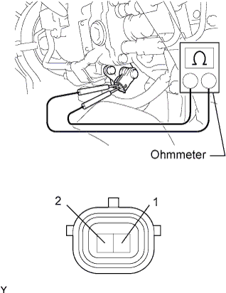
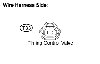
| 1.INSPECT TIMING CONTROL VALVE |
Disconnect the timing control valve connector.
Measure the resistance of the timing control valve.
- Standard resistance:
Tester Connection
| Condition
| Specified Condition
|
1 - 2
| 20°C (68°F)
| 10 to 14 Ω
|
| | REPLACE TIMING CONTROL VALVE |
|
|
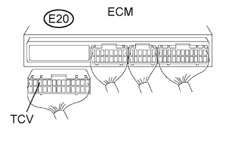
| 2.CHECK ECM (TCV VOLTAGE) |
Disconnect the E20 ECM connector.
Turn the ignition switch ON.
Measure the voltage of the wire harness side connector.
- Standard voltage:
Tester Connection
| Specified Condition
|
E20-11 (TCV) - Body ground
| 9 to 14 V
|
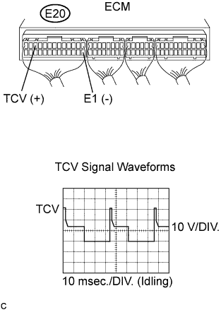
| 3.CHECK ECM (TCV VOLTAGE, SIGNAL) |
Turn the ignition switch ON.
Measure the voltage of the ECM connector.
- Standard voltage:
Tester Connection
| Specified Condition
|
E20-11 (TCV) - E20-14 (E1)
| 9 to 14 V
|
While idling, measure the waveform according to the value(s) in the table below.
- OK:
Tester Connection
| Specified Condition
|
E20-11 (TCV) - E20-14 (E1)
| Correct waveform is as shown
|
Tool Setting
| Condition
|
10 V/DIV., 10 msec./DIV.
| During idling
|
Check the fuel filter (Toyota Fortuner RM0000014YY008X.html).
Visually check the injection pump, each injector and fuel line for fuel leaks.
- OK:
- No leakage
| | REPAIR OR REPLACE PART WITH FUEL LEAKAGE |
|
|
| OK |
|
|
|
| CHECK AND REPLACE INJECTION PUMP ASSEMBLY |
|
| 6.CHECK TIMING CONTROL VALVE (POWER SOURCE) |
Disconnect the T33 timing control valve connector.
Turn the ignition switch ON.
Measure the voltage of the wire harness side connector.
- Standard voltage:
Tester Connection
| Specified Condition
|
T33-1 - Body ground
| 9 to 14 V
|
| | REPAIR OR REPLACE HARNESS OR CONNECTOR (TIMING CONTROL VALVE - ECM) |
|
|
| 7.CHECK HARNESS AND CONNECTOR (ECM - INTEGRATION RELAY [MAIN RELAY]) |
Disconnect the T33 timing control valve connector.
Disconnect the E20 ECM connector.
Disconnect the 1J integration relay connector from the engine room junction block.
Measure the resistance of the wire harness side connectors.
- Standard resistance:
Tester Connection
| Specified Condition
|
T33-1 - 1J-5
| Below 1 Ω
|
E20-11 (TCV) - Body ground
| 10 kΩ or higher
|
T33-1 - Body ground
| 10 kΩ or higher
|
| | REPAIR OR REPLACE HARNESS OR CONNECTOR |
|
|
| OK |
|
|
|
| CHECK ECM POWER SOURCE CIRCUIT |
|