Theft Deterrent System Back Door Courtesy Switch Circuit
DESCRIPTION
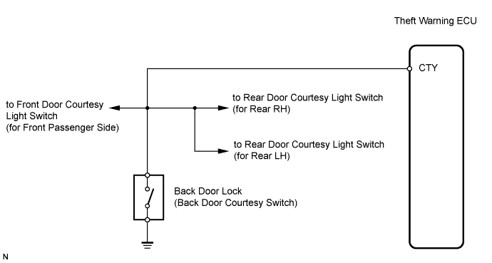
WIRING DIAGRAM
INSPECTION PROCEDURE
INSPECT BACK DOOR LOCK (BACK DOOR COURTESY SWITCH)
CHECK WIRE HARNESS (BACK DOOR LOCK - THEFT WARNING ECU AND BODY GROUND)
THEFT DETERRENT SYSTEM - Back Door Courtesy Switch Circuit |
DESCRIPTION
The theft warning ECU detects the condition of the back door courtesy switch.
WIRING DIAGRAM
INSPECTION PROCEDURE
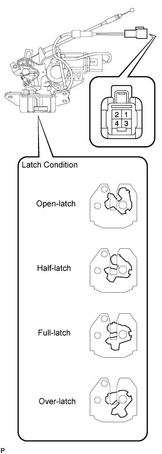
| 1.INSPECT BACK DOOR LOCK (BACK DOOR COURTESY SWITCH) |
Remove the door lock.
Measure the resistance of the switch.
- Standard resistance:
Tester Connection
| Switch Condition
| Specified Condition
|
1 - 2
| Open-latch (ON)
| Below 1 Ω
|
1 - 2
| Half-latch (ON)
| Below 1 Ω
|
1 - 2
| Full-latch (OFF)
| 10 kΩ or higher
|
1 - 2
| Over-latch (OFF)
| 10 kΩ or higher
|
| 2.CHECK WIRE HARNESS (BACK DOOR LOCK - THEFT WARNING ECU AND BODY GROUND) |
Disconnect the B9 switch connector.
Disconnect the T16 ECU connector.
Measure the resistance of the wire harness side connectors.
- Standard resistance:
Tester Connection
| Specified Condition
|
B9-2 - T16-7 (CTY)
| Below 1 Ω
|
B9-1 - Body ground
| 10 kΩ or higher
|
| | REPAIR OR REPLACE HARNESS AND CONNECTOR |
|
|
| OK |
|
|
|
| PROCEED TO NEXT CIRCUIT INSPECTION SHOWN IN PROBLEM SYMPTOMS TABLE |
|