Condenser (For 1Gr-Fe) -- Installation |
| 1. INSTALL COOLER CONDENSER ASSEMBLY |
Install the cooler condenser.
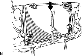 |
| 2. INSTALL RADIATOR SUPPORT UPPER |
Install the radiator support with the 6 bolts.
- Torque:
- 5.5 N*m{ 56 kgf*cm, 49 in.*lbf} for bolt A
- 5.4 N*m{ 55 kgf*cm, 47 in.*lbf} for bolt B
 |
| 3. INSTALL HOOD LOCK ASSEMBLY |
Install the hood lock with the 3 bolts.
 |
| 4. CONNECT AIR CONDITIONING TUBE & ACCESSORY ASSEMBLY |
Remove the vinyl tape attached to the A/C tube and connecting part of the cooler condenser.
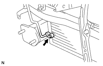 |
Sufficiently apply compressor oil to a new O-ring and the fitting surface of the A/C tube.
- Compressor oil:
- ND-OIL 8 or equivalent
Install the O-ring on the A/C tube.
Install the A/C tube on the cooler condenser with the bolt.
- Torque:
- 5.4 N*m{ 55 kgf*cm, 47 in.*lbf}
| 5. INSTALL NO. 1 COOLER REFRIGERANT DISCHARGE HOSE |
Remove the vinyl tape attached to the discharge hose and connecting part of the cooler condenser.
Sufficiently apply compressor oil to a new O-ring and the fitting surface of the discharge hose.
- Compressor oil:
- ND-OIL 8 or equivalent
Install the O-ring on the discharge hose.
Install the discharge hose on the cooler condenser with the bolt.
- Torque:
- 5.4 N*m{ 55 kgf*cm, 47 in.*lbf}
 |
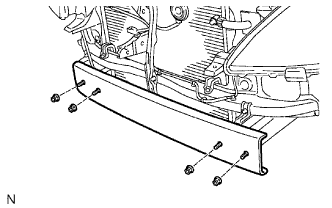
| 6. INSTALL FRONT BUMPER REINFORCEMENT |
Install the reinforcement with the 4 nuts.
- Torque:
- 67 N*m{ 683 kgf*cm, 49 ft.*lbf}
 |
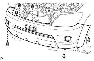
| 7. INSTALL FRONT BUMPER COVER |
Put protective tape under the front fender.
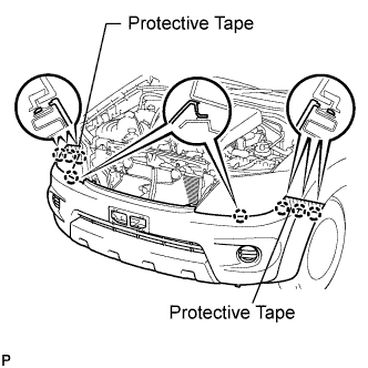 |
Connect the 2 fog light connectors.
Attach the 8 claws to install the cover.
Install the 11 clips.
 |
| 8. CONNECT CABLE TO NEGATIVE BATTERY TERMINAL |
| 9. CHARGE REFRIGERANT |
- SST
- 09985-20010(09985-02130,09985-02150,09985-02090,09985-02110,09985-02010,09985-02050,09985-02060,09985-02070)
Perform vacuum purging using a vacuum pump.
Charge refrigerant HFC-134a (R134a).
- Standard:
- 750 +-30 g (26.45 +-1.05 oz.)
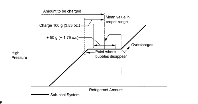
- NOTICE:
- Do not operate the cooler compressor before charging refrigerant as the cooler compressor will not work properly without any refrigerant, and will overheat.
- Approximately 100 g (3.53 oz.) of refrigerant may need to be charged after bubbles disappear. The refrigerant amount should be checked by quantity, and not with the sight glass.
| 10. WARM UP ENGINE |
Warm up the engine at less than 1,850 rpm for 2 minutes or more after charging refrigerant.
- NOTICE:
- Be sure to warm up the compressor when turning the A/C switch ON after removing and installing the cooler refrigerant lines (including the compressor), to prevent damage to the compressor.
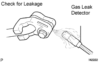
| 11. CHECK FOR LEAKAGE OF REFRIGERANT |
After recharging the refrigerant gas, check for refrigerant gas leakage using a halogen leak detector.
After recharging the refrigerant gas, prepare the vehicle for a refrigerant gas leakage check by making sure the following conditions are met.
The ignition switch is OFF.
The vehicle is in a place with good air ventilation and without any volatile gases, such as evaporated gasoline or exhaust gas. The detector is very sensitive gases, If volatile gases are unavoidable, the vehicle must be lifted up.
Some refrigerant is remaining in the refrigerant system.
The compressor is OFF and its pressure is approximately 392 to 588 kPa (4 to 6 kgf/cm2).
Using a gas leak detector, check the refrigerant line for leakage.
 |
If a gas leak is not detected on the drain hose, remove the blower motor control (blower resistor) from the cooling unit. Insert the gas leak detector sensor into the unit and perform the test.
Disconnect the connector and leave the pressure switch on for approximately 20 minutes. Bring the gas leak detector close to the pressure switch and perform the test.