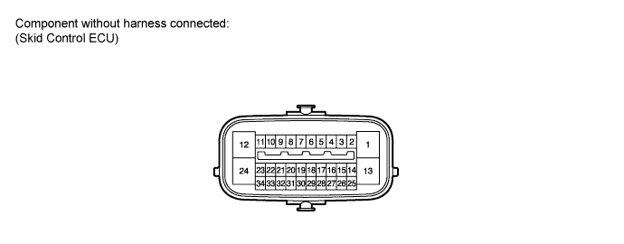
Vehicle Stability Control System Terminals Of Ecu
TERMINALS OF ECU
TERMINAL INSPECTION
Vehicle Stability Control System -- Terminals Of Ecu |
Terminal No. (Symbol)
| Terminal Description
|
1 (GND1)
| Skid control ECU ground
|
2 (STP)
| Stop light switch input
|
3 (IND)
| Slip indicator light output
|
4 (RL-)
| Rear wheel speed LH (-) signal input
|
5 (RL+)
| Rear wheel speed LH (+) power supply output
|
6 (FR-)
| Front wheel speed RH (-) signal input
|
7 (FR+)
| Front wheel speed RH (+) power supply output
|
8 (BRL)
| Brake warning light output
|
9 (EXI4)*1
| L4 detection switch input
|
10 (WA)
| ABS warning light output
|
12 (+BS)
| Solenoid relay power supply
|
13 (GND2)
| Pump motor ground
|
14 (CANL)
| CAN communication line L
|
15 (VSCW)
| VSC warning light output
|
16 (RR-)
| Rear wheel speed RH (-) signal input
|
17 (RR+)
| Rear wheel speed RH (+) power supply output
|
18 (FL-)
| Front wheel speed LH (-) signal input
|
19 (FL+)
| Front wheel speed LH (+) power supply output
|
20 (EXI)*1
| Center differential lock signal input
|
21 (BZ)
| Skid control buzzer output
|
24 (BM)
| Motor relay power supply
|
25 (CANH)
| CAN communication line H
|
27 (FSW+)
| Brake pedal load sensing switch input
|
28 (EXI3)
| Rearr differential lock signal input
|
29 (PKB)
| Parking brake switch input
|
30 (CSW)
| VSC OFF switch input
|
32 (P)*2
| Neutral start switch P position signal input
|
33 (TS)
| Sensor check input
|
34 (IG1)
| ECU power supply
|
- *1: for 4WD
- *2: for A/T
Disconnect the connector and measure the voltage or resistance on the wire harness side.
- HINT:
- Voltage cannot be measured with the connector connected to the skid control ECU as the connector is watertight.
Terminal No. (Symbol)
| Wiring Color
| Terminal Description
| Condition
| Specified Condition
|
S25-1 (GND1) - Body ground
| W-B - Body ground
| Skid control ECU ground
| Always
| Below 1 Ω
|
S25-2 (STP) - Body ground
| G-W - Body ground
| Stop light switch input
| Stop light switch ON → OFF
(Brake pedal depressed → released)
| 11 to 14 V
→ Below 1.5 V
|
S25-12 (+BS) - Body ground
| W-R - Body ground
| Solenoid relay power supply
| Always
| 11 to 14 V
|
S25-13 (GND2) - Body ground
| W-B - Body ground
| Pump motor ground
| Always
| Below 1 Ω
|
S25-21 (BZ) - Body ground
| B-Y - Body ground
| Skid control buzzer output
| Ignition switch ON, buzzer not sounding
| 6 to 10 V
|
S25-24 (BM) - Body ground
| R - Body ground
| Motor relay power supply
| Always
| 11 to 14 V
|
S25-27 (FSW+) - Body ground
| L - Body ground
| Brake pedal load sensing switch input
| Brake pedal load sensing switch OFF → ON
(Brake pedal depressed → released)
| 950 to 1050 Ω → 203 to 223 Ω
|
S25-29 (PKB) - Body ground
| L-O - Body ground
| Parking brake switch input
| Ignition switch ON, parking brake switch ON → OFF
| Below 1 Ω → 10 kΩ or higher
|
S25-30 (CSW) - Body ground
| R-L- Body ground
| VSC OFF switch input
| VSC OFF switch held ON → OFF (Released)
| Below 1 Ω → 10 kΩ or higher
|
S25-34 (IG1) - Body ground
| B - Body ground
| ECU power supply
| Ignition switch on
| 11 to 14 V
|
